Shell for a hearing device
- Summary
- Abstract
- Description
- Claims
- Application Information
AI Technical Summary
Benefits of technology
Problems solved by technology
Method used
Image
Examples
first embodiment
[0041]FIG. 1 illustrates a shell 10 for a hearing device according to the invention, and comprises a closed end (in which ultimately at least one hole will be formed for a sound outlet and / or a wax guard) situated on the left-hand side of FIG. 1, and an open end situated on the right-hand side of FIG. 1. The shell comprises a sub-shell 11 situated inside a thermoformed hull 12. In the view of FIG. 1, the thermoformed hull 12 has been cut away so as to show the structure of the shell 10. Shell 10 may be a shell for an in-the-ear hearing device, particularly an Invisible In the Canal (iiC) hearing device, or may likewise be a shell of an earpiece for a behind-the-ear hearing device.
[0042]Sub-shell 11 is fabricated of a relatively rigid biocompatible material, such as a polymer material or a ceramic-filled polymer material such as UV- or visible light cuarble acrylic resins, and is responsible for the majority of the structural integrity and stiffness of the shell 10. As such, the wall...
second embodiment
[0047]FIG. 3 illustrates a shell 20 for a hearing device according to the invention, which differs from the embodiment of FIGS. 1 and 2 in that the thermoformed hull 22 is situated on the interior of sub-shell 21. This arrangement provides even greater relief from pressure on the ear canal in the areas of openings 23, since the surface of thermoformed hull 22 is below the outer surface of sub-shell 21 by an amount equal to the wall thickness of the sub-shell 21. This, however, comes at the cost of reducing the space available for hearing device components on the interior of the shell 20 in the region of the openings 23.
[0048]FIG. 4, in analogy to FIG. 2, illustrates a cross-section of shell 20 along line B-B of FIG. 3, illustrating clearly the arrangement of sub-shell 21 and thermoformed hull 22 on the interior surface thereof. Openings 23 are clearly visible, covered on their interior side by thermoformed hull 22. The above-mentioned comments regarding the joining of sub-shell 11 a...
third embodiment
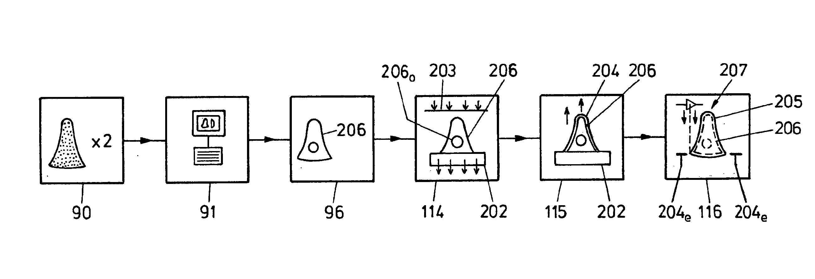
[0073]the method is represented by the upper track, labelled “A”, on FIG. 11. After the step of thermoforming the polymer film 203 to create the thermoformed polymer film 204, the thermoformed polymer film is attached to the thermoforming mould 200, e.g. by ultrasonic welding. Alternatively, an adhesive may be applied to the polymer film 203 and / or to the thermoforming mould 200 before thermoforming. Subsequently, in step 110, the thermoforming mould 200 has any easily removable sections broken out of it, and is machined as necessary so as to fabricate the sub-shell 206 in situ in the thermoformed hull 205, and the shell is then finished in step 98 as in FIG. 9, and is ready to be assembled into part of a hearing device. This has the advantage that the thermoformed hull 205 is formed in intimate contact with what will become the sub-shell 206, thus improving the matching accuracy of the sub-shell 206 and the thermoformed hull 205. Furthermore, no additional die or sub-shell is requi...
PUM
 Abstract
Description
Claims
Application Information
 - R&D
- Intellectual Property
- Life Sciences
- Materials
- Tech Scout
- Unparalleled Data Quality
- Higher Quality Content
- 60% Fewer Hallucinations
Browse by: Latest US Patents, China's latest patents, Technical Efficacy Thesaurus, Application Domain, Technology Topic, Popular Technical Reports.
© 2025 PatSnap. All rights reserved.Legal|Privacy policy|Modern Slavery Act Transparency Statement|Sitemap|About US| Contact US: help@patsnap.com


