Thermal energy harvesting system

a technology of thermal energy harvesting and energy harvesting, which is applied in the direction of closed-cycle machines/engines, hot gas positive displacement engine plants, etc., can solve the problems of ozone damaging greenhouse gas generation, large effort and cost, and difficulty in recovering and processing such non-renewable natural resources

Active Publication Date: 2015-12-10
THE UNIVERSITY OF AKRON
View PDF3 Cites 7 Cited by
  • Summary
  • Abstract
  • Description
  • Claims
  • Application Information

AI Technical Summary

Benefits of technology

The present invention provides a thermal energy harvesting system that can convert the rotation of a shaft into electrical power. The system includes a frame and two elongated tubes with shape memory sections enclosed therein. When the tubes are filled with hot or cold fluid, the shape memory sections expand or contract to rotate the shaft in a specific direction. The system also includes inlet valves to control the flow of hot and cold fluid, and a controller to manage the flow of fluid. The system can generate electrical power from the rotation of the shaft when the tubes are filled with hot or cold fluid.

Problems solved by technology

The recovery and processing of such non-renewable natural resources requires substantial efforts and cost.
In addition, energy generation systems that utilize on such natural resources to generate electricity, typically output unwanted pollutants as byproducts, which contribute to the generation of ozone damaging greenhouse gases.
In addition, while alternative methods of energy generation have been explored, such as fracking, wind turbines, solar panels, and nuclear plants, such methods suffer from various drawbacks.
Moreover, such alternative energy generation methods are unable to recover wasted thermal energy or heat that is often a substantially byproduct of many energy generation systems.
Unfortunately, traditional waste heat recovery techniques are unable to convert such low-grade heat into electricity.

Method used


Image

  • Thermal energy harvesting system
  • Thermal energy harvesting system
  • Thermal energy harvesting system

Examples


Embodiment Construction

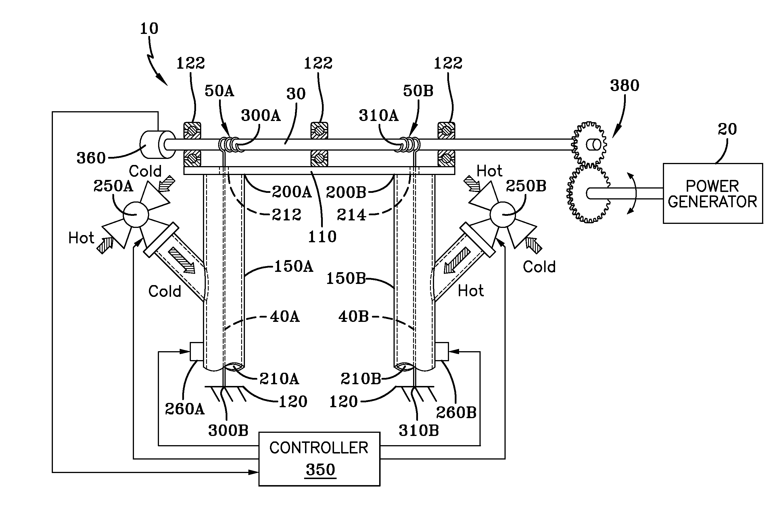
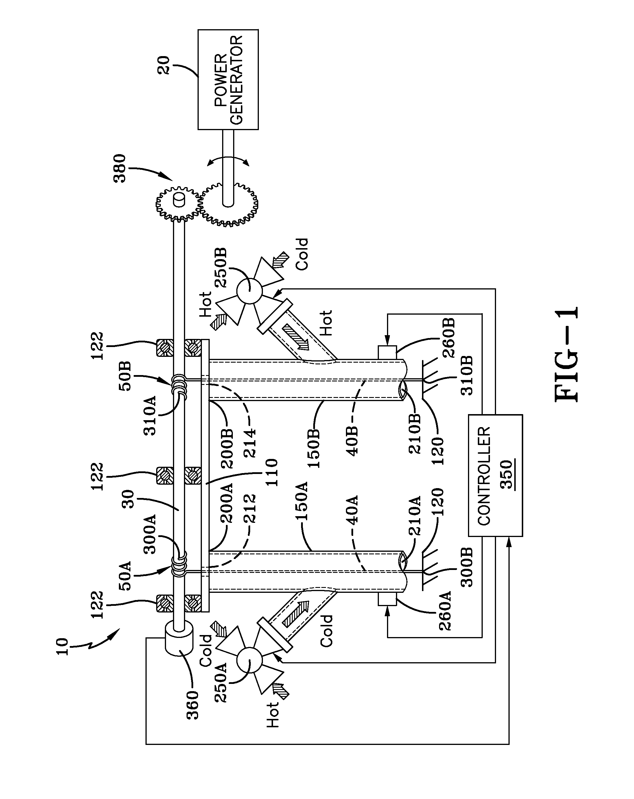
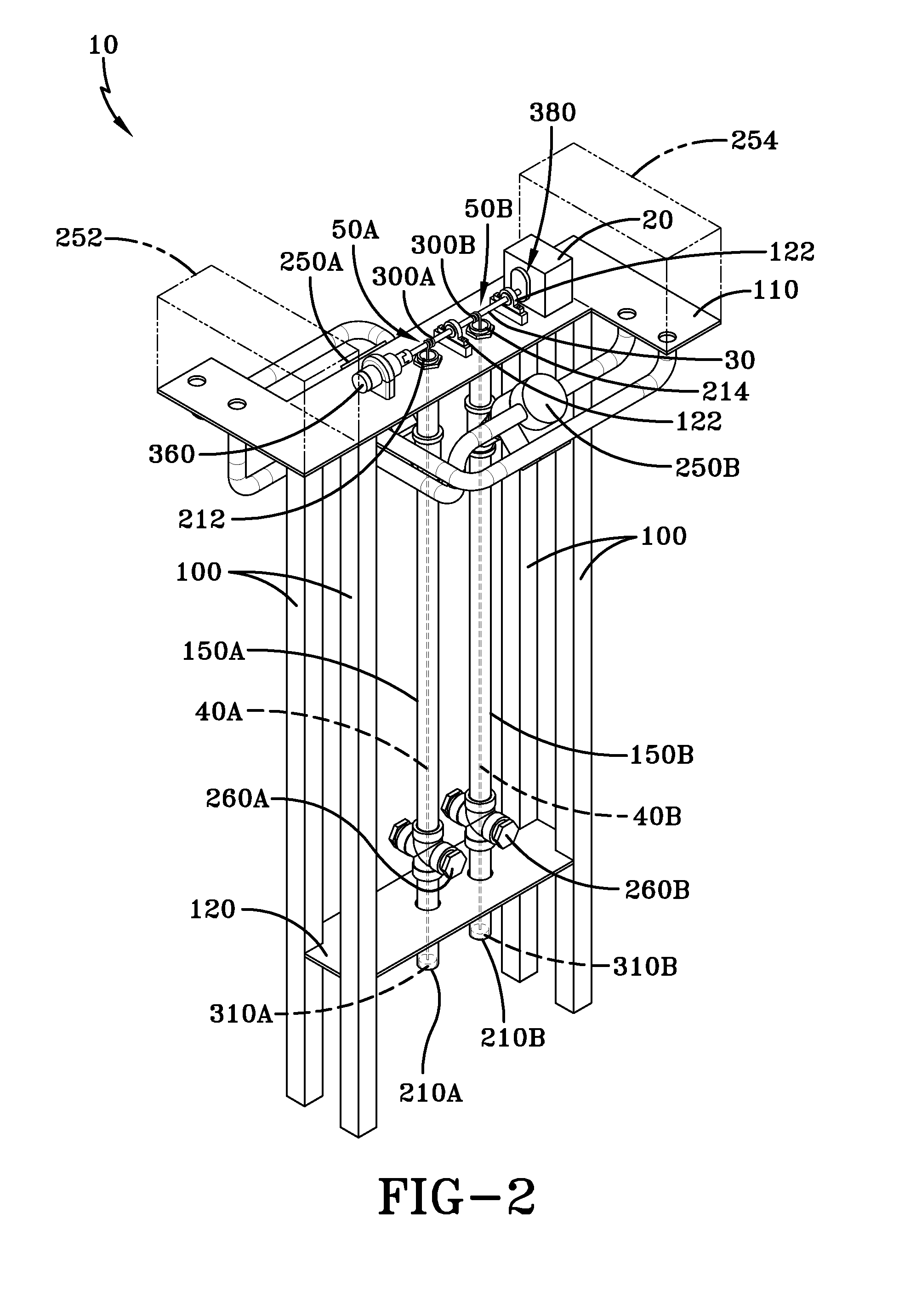
[0029]A thermal energy harvesting system is generally referred to by numeral 10, as shown in FIGS. 1-4 of the drawings. The thermal energy harvesting system 10 includes a power generator 20 that is configured to generate electrical power or energy when a shaft 30 that is in mechanical communication with the generator 20 is rotated in either direction (e.g. clockwise or counterclockwise). Coupled to the shaft 30 is a first shape memory section 40A and a second shape memory section 40B, as shown clearly in FIGS. 1 and 2. For the purposes of the following discussion, the shape memory sections 40A-B are formed from any elongated section of shape memory material, shape memory alloy (SMA), or any other material that is capable of taking on one shape (e.g. expanded in length) when cooled and another shape (e.g. contracted in length) when heated. Continuing, one end of each of the shape memory sections 40A-B includes respective pre-shaped coil sections 50A-B, which may take on a coiled or h...


PUM


Abstract

A thermal energy harvesting system includes a pair of shape memory sections formed of shape memory alloy (SMA) material that are each disposed within a tube. The shape memory sections are fixed in position at one end and are attached at another end to a rotating shaft that is in mechanical communication with a power generator. Fluid inlet valves are provided in each housing and are each controlled to alternatingly supply hot and cold fluid to the tubes to selectively heat and cool the shape memory sections. This results in the cyclical contraction and expansion of the shape memory sections, which causes oscillating rotation of the shaft that is converted by the power generator into electrical power.

Description

CROSS-REFERENCE TO RELATED APPLICATIONS[0001]This application claims priority from International Application No. PCT / US2014 / 011678 filed Jan. 15, 2014, which claims priority from U.S. Provisional Application No. 61 / 752,634 filed on Jan. 15, 2013, whereby the content of each application is incorporated herein by reference.TECHNICAL FIELD[0002]Generally, the present invention relates to energy generation systems. In particular, the present invention is directed to a thermal energy harvesting system. More particularly, the present invention relates to a thermal energy harvesting system that generates energy by alternatingly subjecting sections of shape memory alloy (SMA) to hot and cold temperatures.BACKGROUND OF THE INVENTION[0003]Current energy generation systems are configured to generate power from non-renewable natural resources, such as oil and natural gas. The recovery and processing of such non-renewable natural resources requires substantial efforts and cost. In addition, ener...

Claims


Application Information

Patent Timeline
Patent Type & Authority Applications(United States)
IPC IPC(8): F03G7/06
CPCF03G7/065
Inventor ENGEBERG, ERIK D.HARIHARAN, SUBRAMANIYA I.KENT, BENJAMIN A.LAVERY, JOHN
Owner THE UNIVERSITY OF AKRON
Why Eureka
Try Eureka