
Drive circuit device for flicker-free LED

a technology of flicker-free led and drive circuit, which is applied in the direction of electrical equipment, lighting equipment, light sources, etc., can solve the problems of low reliability, low production cost, and unstable led current, and achieve high reliability, high stability, and low production cost

Inactive Publication Date: 2015-12-03
ARCADIE TECH
View PDF1 Cites 10 Cited by
  • Summary
  • Abstract
  • Description
  • Claims
  • Application Information

AI Technical Summary

Benefits of technology

The present invention aims to provide a driver circuit for flicker-free LEDs that can withstand temperature changes, has low production costs, high reliability, and stability. Additionally, it has a high power factor, reducing the burden on users and increasing efficiency in use.

Problems solved by technology

Moreover, a DC converter is also required for converting AC power into DC power to drive the LEDs, but the conversion of a voltage causes a pulsating current which make the LED current unstable and produce flicker.
However, a high cost is still existed in manufacturing LED lights with IC to meet the high reliability, high stability and a high power factor.
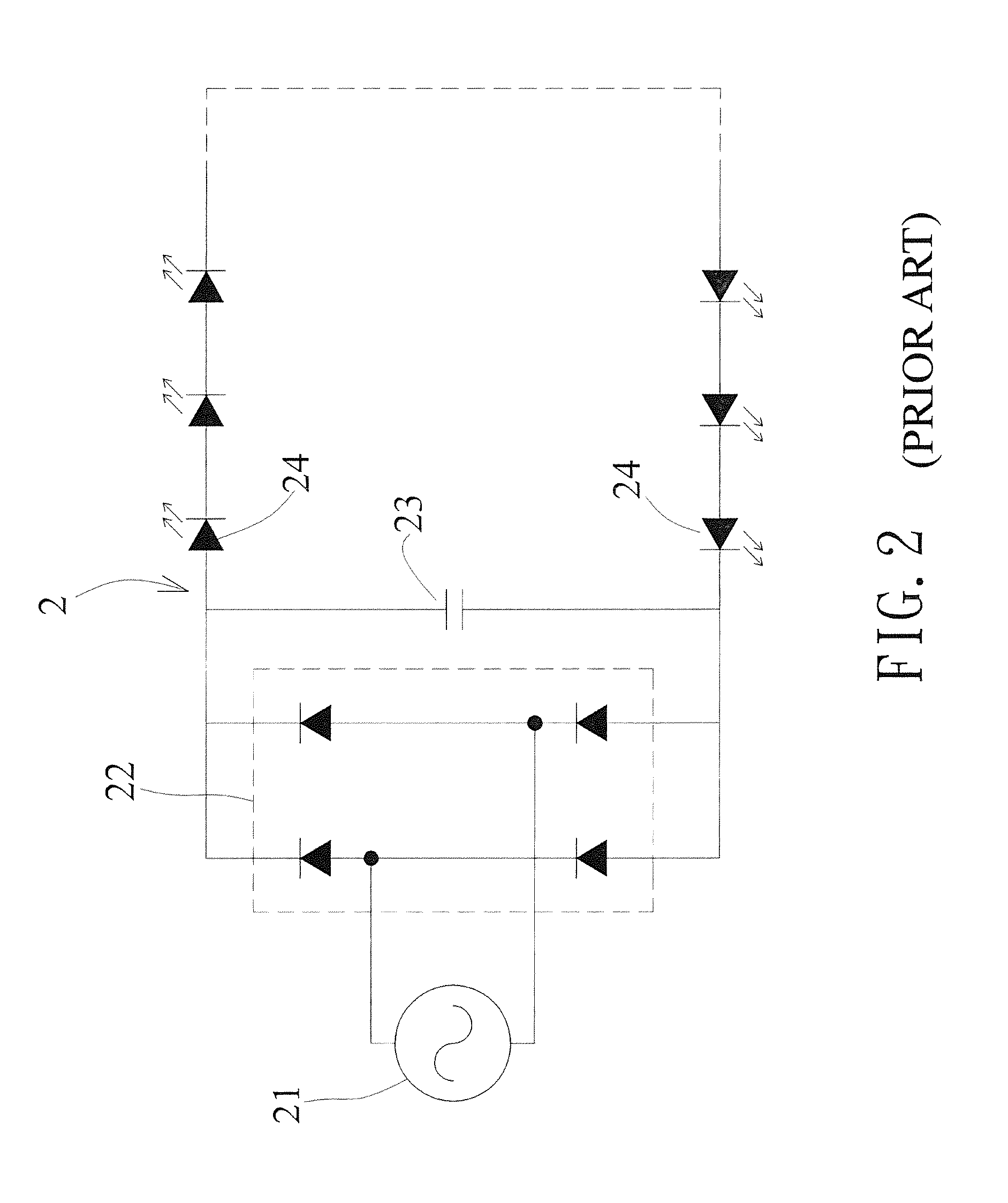
Although aforementioned structure has a rectifier in series with a step-down capacitor for driving LEDs to solve a problem of flicker, it also has some disadvantages as followings:1. The step-down capacitor is made of a high voltage electrolytic capacitor, resulting in a high cost in manufacturing an overall circuit.2. The step-down capacitor made of a high voltage electrolytic capacitor can hardly withstand a high temperature caused by LEDs and a temperature lower than −20 degrees.3. The step-down capacitor made of a high voltage electrolytic capacitor only has a power factor of about 50%, which is not suitable for products in need of a higher power factor.

Method used


Image

  • Drive circuit device for flicker-free LED
  • Drive circuit device for flicker-free LED
  • Drive circuit device for flicker-free LED

Examples


Embodiment Construction

[0014]Hereinafter, an exemplary embodiment of the present invention will be described in detail with reference to the accompanying drawings.

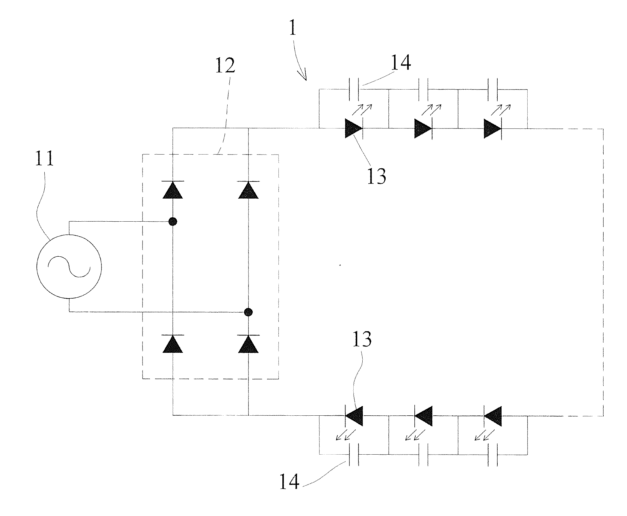
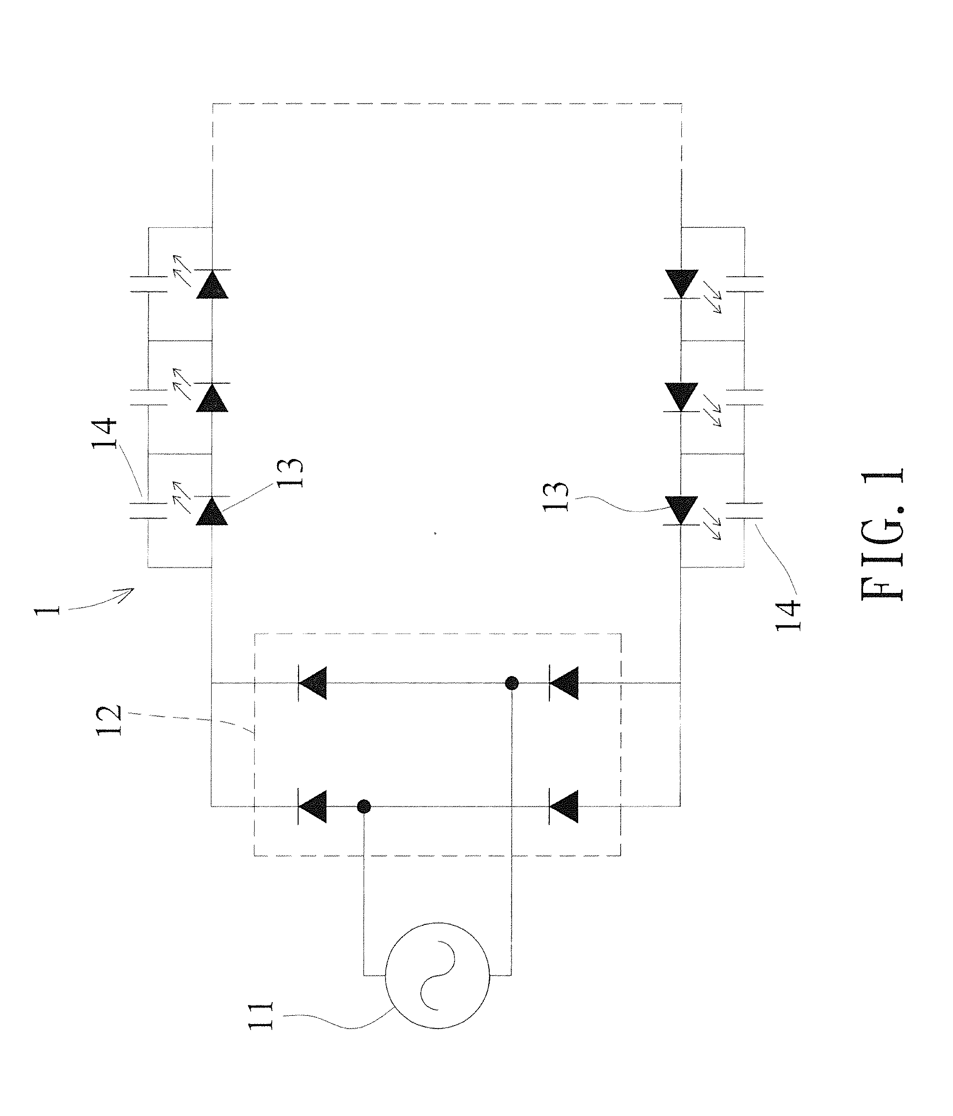
[0015]First, referring to FIG. 1, a schematic diagram showing a circuit according to the present invention is revealed. A drive circuit device for a flicker-free LED, comprising a drive circuit (1) having a rectifier (12) connecting to an AC power supply (11) and to a plurality of LEDs (13) in series, wherein each of the plurality of LEDs (13) is disposed in parallel with a multilayer capacitor (14).

[0016]Accordingly, an input of supply mains from the AC power supply (11) of the drive circuit (1) into the rectifier (12) is rectified, and then the rectified supply mains is transmitted to the plurality of LEDs (13) and the multilayer capacitor (14). The multilayer capacitor (14) further filters the rectified supply mains for supplying the plurality of LEDs (13), allowing the plurality of LEDs (13) to emit light.

[0017]According to the above descrip...


PUM


Abstract

A drive circuit device for a flicker-free LED is revealed. It comprises a drive circuit having a rectifier connecting to an AC power supply and to a plurality of LEDs in series, wherein each of the plurality of LEDs is disposed in parallel with a multilayer capacitor.

Description

BACKGROUND OF THE INVENTION[0001]1. Field of the Invention[0002]The present invention relates to a drive circuit device for a flicker-free LED. It can withstand large temperature changes and has a low production cost, high reliability, high stability and a high power factor, so as to reduce the burden on users and increase efficiency in use.[0003]2. Description of Related Art[0004]Light-Emitting Diodes (LEDs) have many advantages including low energy consumption, small size, long lifetime, high reaction rate, shock resistance, and monochromaticity. Therefore, LEDs have been widely accepted and used by all walks of life for lighting purposes, and many manufacturers began endeavoring to do various development and improvement of LEDs. In use of LEDs light for illumination, some factors are needed to be considered, including cost, reliability, stability and power factor. Moreover, a DC converter is also required for converting AC power into DC power to drive the LEDs, but the conversion...

Claims


Application Information

Patent Timeline
IPC IPC(8): H05B33/08H05B44/00
CPCH05B33/0809H05B33/0821H05B45/42
Inventor HUANG, TAI-HSIANGHUANG, KUAN-HSIANG
Owner ARCADIE TECH
Learn More