
Transmission device, reception device and communication system

a technology of transmission device and reception device, which is applied in the direction of multiplex communication, orthogonal multiplex, wireless commuication services, etc., can solve the problems of limiting the improvement of the frequency usage efficiency of mu-mimo using linear precoding, and affecting the transmission efficiency of the transmitting device, etc., to achieve excellent effect and improve transmission characteristics

Inactive Publication Date: 2015-12-03
SHARP KK +1
View PDF5 Cites 23 Cited by
  • Summary
  • Abstract
  • Description
  • Claims
  • Application Information

AI Technical Summary

Benefits of technology

The present invention improves transmission characteristics in MU-MIMO transmission using non-linear precoding by combining packets. This results in a better overall effect of the transmission.

Problems solved by technology

However, the number of the receive antennas which are able to be arranged in a terminal device serving as a reception device is limited.
However, unless orthogonality of channels of the terminal devices which are subjected to spatial multiplexing is high, the IUI is not able to be suppressed effectively, so that there is a limit on the improvement of the frequency usage efficiency in MU-MIMO using the linear precoding (linear MU-MIMO).
However, the non-linear precoding has a problem that in a case where a signal to noise power ratio (SNR) or a carrier to noise power ratio (CNR), a signal to interference plus noise power ratio (SINR) or a carrier to interference plus noise power ratio (CINR) is low, characteristic degradation called modulo-loss is caused that a reception signal point is detected as an erroneous signal point as a result of modulo operation which is performed on a reception side for one received over a border line of the modulo operation due to noise, inter-cell-interference or the like (NPL 3)
With the ARQ, redundancy of coding is small and high reliability is achieved with relatively simple processing, but retransmission occurs frequently if the error is increased and transmission efficiency is rapidly reduced.

Method used


Image

  • Transmission device, reception device and communication system
  • Transmission device, reception device and communication system
  • Transmission device, reception device and communication system

Examples


first embodiment

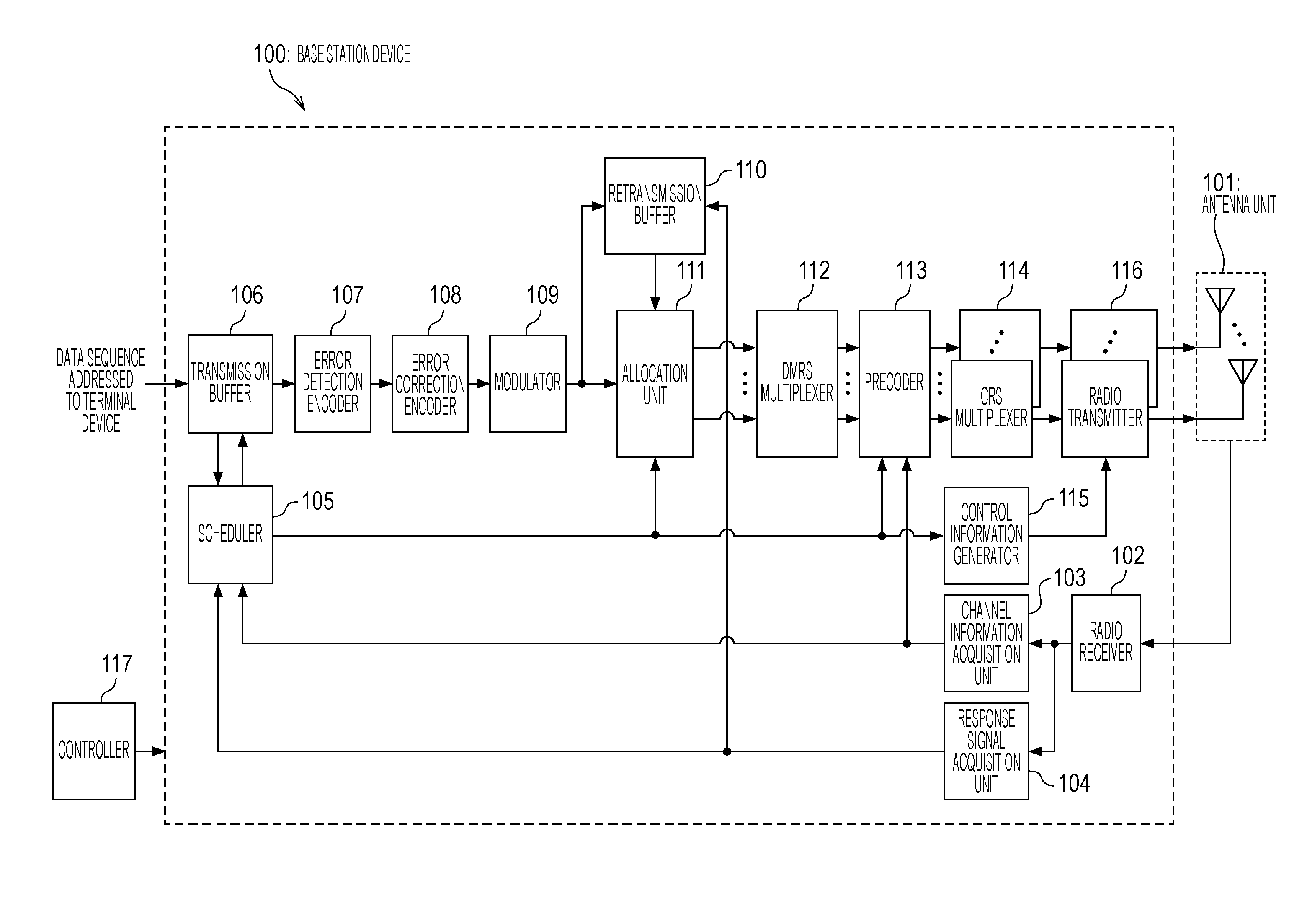
[0036]In a communication technology according to the present embodiment, with respect to a plurality of reception devices (terminal devices), a transmission device (base station device) performs MU-MIMO transmission for transmitting transmission data addressed to these plurality of reception devices simultaneously by performing spatial multiplexing. Description will be given by taking, as an example, a communication system in which the transmission device performs the transmission at this time by applying signal processing for suppressing in advance inter-user interference (IUI) which is caused between signals (streams) addressed to each of the reception devices by non-linear precoding to the transmission data.

[0037]FIG. 1 is a schematic configuration view showing one example of a communication system in the embodiment of the present invention.

[0038]The communication system in the example of FIG. 1 is configured by a base station device 100 which is a transmission device for MU-MIMO...

second embodiment

[0120]Description will be given for a communication technology according to the present embodiment by taking the communication system of FIG. 1 as an example in the same manner as the first embodiment. Moreover, description will be given in the present embodiment by taking a case where Tomlinson-Harashima precoding (THP) is used as non-linear precoding as an example.

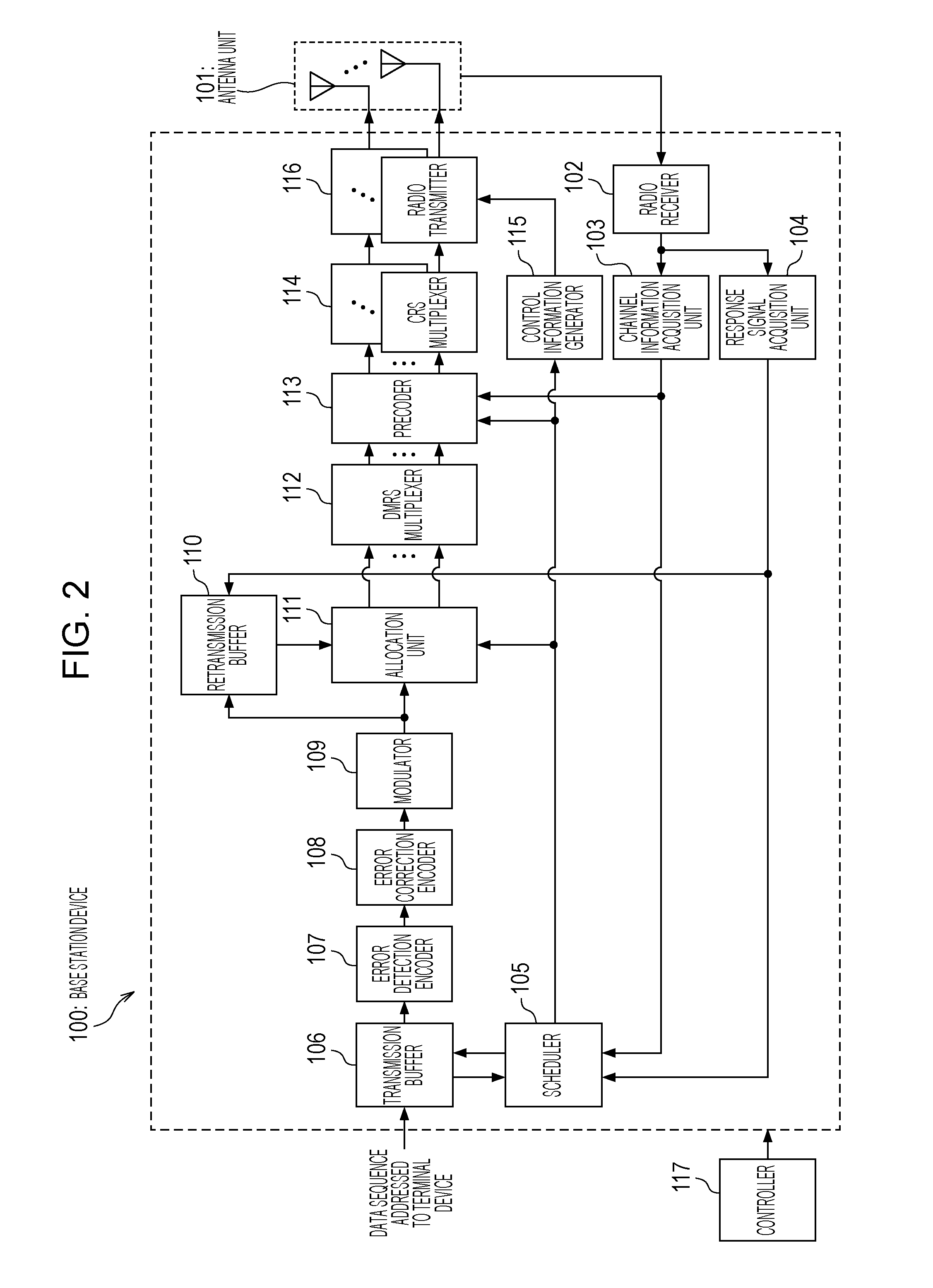
[0121]A configuration of the base station device 100 according to the present embodiment is same as that of the base station device 100 of FIG. 2 of the first embodiment, and a configuration of the precoder 113 is different. Hereinafter, description for same parts as those of the first embodiment will be omitted and description will be given for different parts. Further, a configuration of the terminal device 400 according to the present embodiment is the same as that of the terminal device 400 of FIG. 4 of the first embodiment, so that description thereof will be omitted.

[0122]In a case of receiving the NAK from any of ...

third embodiment

[0145]Description will be given for a communication technology according to the present embodiment by taking the communication system of FIG. 1 as an example in the same manner as the first embodiment.

[0146]A configuration of the base station device 100 according to the present embodiment is same as that of the base station device 100 of FIG. 2 of the first embodiment, and the scheduler 105, the error correction encoder 108, the precoder 113 and the control information generator 115 operate differently. Hereinafter, description for same parts as those of the first embodiment will be omitted and description will be given for different parts.

[0147]The base station device 100 in the present embodiment notifies each of the terminal devices 400 of information for specifying, in the case of transmitting a packet, a combination of coding bits transmitted with this packet, that is, a coding bit sequence to be transmitted actually among coding bit sequences which are transmission data sequen...


PUM


Abstract

It is intended to provide a transmission device, a reception device and a communication system capable of improving transmission characteristics by performing packet combining by HARQ in MU-MIMO transmission using non-linear precoding.In a case of receiving NAK from any of terminal devices (400), a base station device (100) retransmits a packet, in which an error occurs, addressed to this terminal device. The base station device (100) transmits the data to be retransmitted together with other transmission data addressed to a different terminal device or addressed to the own terminal device by spatial multiplexing transmission with MU-MIMO. At this time, for the retransmission data, precoding is performed such that a perturbation term same as a perturbation term which has been added to this data by non-linear precoding at the time of initial transmission is added.

Description

TECHNICAL FIELD[0001]The present invention relates to a transmission device, a reception device and a communication system, in which a packet transmitted being subjected to precoding in the transmission device is received and error detection of the packet is performed to make an automatic retransmission request.BACKGROUND ART[0002]As a technology capable of substantially improving frequency usage efficiency, a multiple input multiple output (MIMO) technology for performing radio transmission by using a plurality of transmit and receive antennas is attracting attention and is being put into practical use in a cellular system, a radio LAN system or the like.[0003]A quantity of improvement of the frequency usage efficiency by the MIMO technology is proportional to the number of the transmit and receive antennas. However, the number of the receive antennas which are able to be arranged in a terminal device serving as a reception device is limited. Thus, multi-user MIMO (MU-MIMO) of down...

Claims


Application Information

Patent Timeline
Patent Type & Authority Applications(United States)
IPC IPC(8): H04L5/00H04L1/18H04B7/06H04B7/04H04J11/00
CPCH04L5/0026H04B7/0456H04B7/0452H04L1/1893H04B7/0697H04L1/1812H04J11/0033H04W16/28H04L25/03898H04L1/1845
Inventor ONODERA, TAKASHITOMEBA, HIROMICHIKUBOTA, MINORUMAEHARA, FUMIAKITAKAHATA, FUMIO
Owner SHARP KK
Learn More