Optical polymer and optical element obtained by forming thereof
a technology of optical polymer and optical element, applied in the field of optical polymer, can solve the problems of difficult to increase the optically effective area, non-uniform birefringence, wax may bleed out from the surface, etc., and achieves the effects of small diameter, small diameter, and large optically effective area
- Summary
- Abstract
- Description
- Claims
- Application Information
AI Technical Summary
Benefits of technology
Problems solved by technology
Method used
Image
Examples
example 1
[0106]A polymerization reactor which had been dried and in which the internal atmosphere had been replaced by nitrogen, was charged with 7 parts (1% based on the total amount of the monomers used for polymerization) of a monomer mixture including 70 wt % of methanotetrahydrofluorene (hereinafter abbreviated as “MTF”), 22 wt % of tetracyclododecene (hereinafter abbreviated as “TCD”), and 8 wt % of norbornene (hereinafter abbreviated as “NB”), 1600 parts of dehydrated cyclohexane, 0.6 parts of 1-hexene, 1.3 parts of diisopropyl ether, 0.33 parts of isobutyl alcohol, 0.84 parts of triisobutylaluminum, and 30 parts of a 0.66% cyclohexane solution of tungsten hexachloride. The mixture was stirred at 55° C. for 10 minutes.
[0107]693 parts of the monomer mixture and 72 parts of a 0.77% cyclohexane solution of tungsten hexachloride were continuously added dropwise to the polymerization reactor over 150 minutes with stirring while maintaining the reaction system at 55° C. After completion of ...
example 2
[0115]A norbornene-based polymer was obtained in the same manner as in Example 1, except that a monomer mixture including 65 wt % of MTF, 30 wt % of TCD, and 5 wt % of NB was used as the monomer mixture, and the amount of 1-hexene was changed to 0.55 parts.
[0116]The conversion ratio of the monomers into a polymer was 99.9%. The resulting norbornene-based polymer had a weight average molecular weight (Mw) of 25,000, a molecular weight distribution (Mw / Mn) of 1.72, a hydrogenation ratio of 99.9%, and a glass transition temperature (Tg) of 145° C.
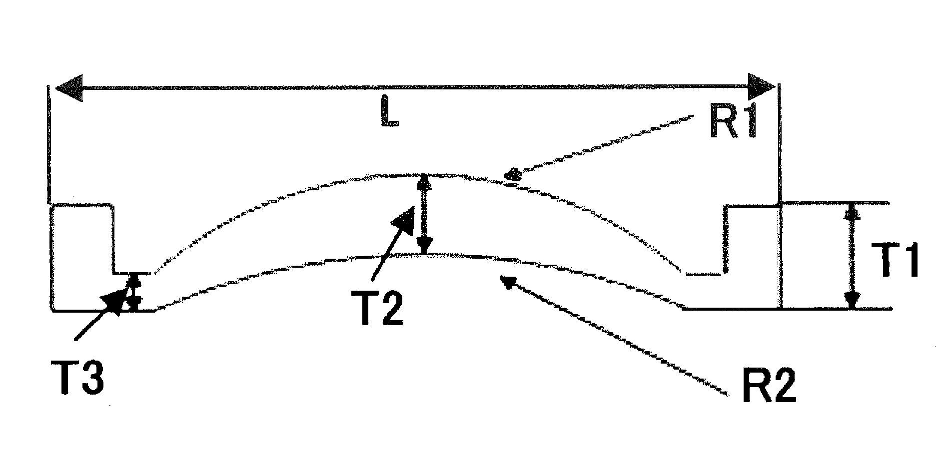
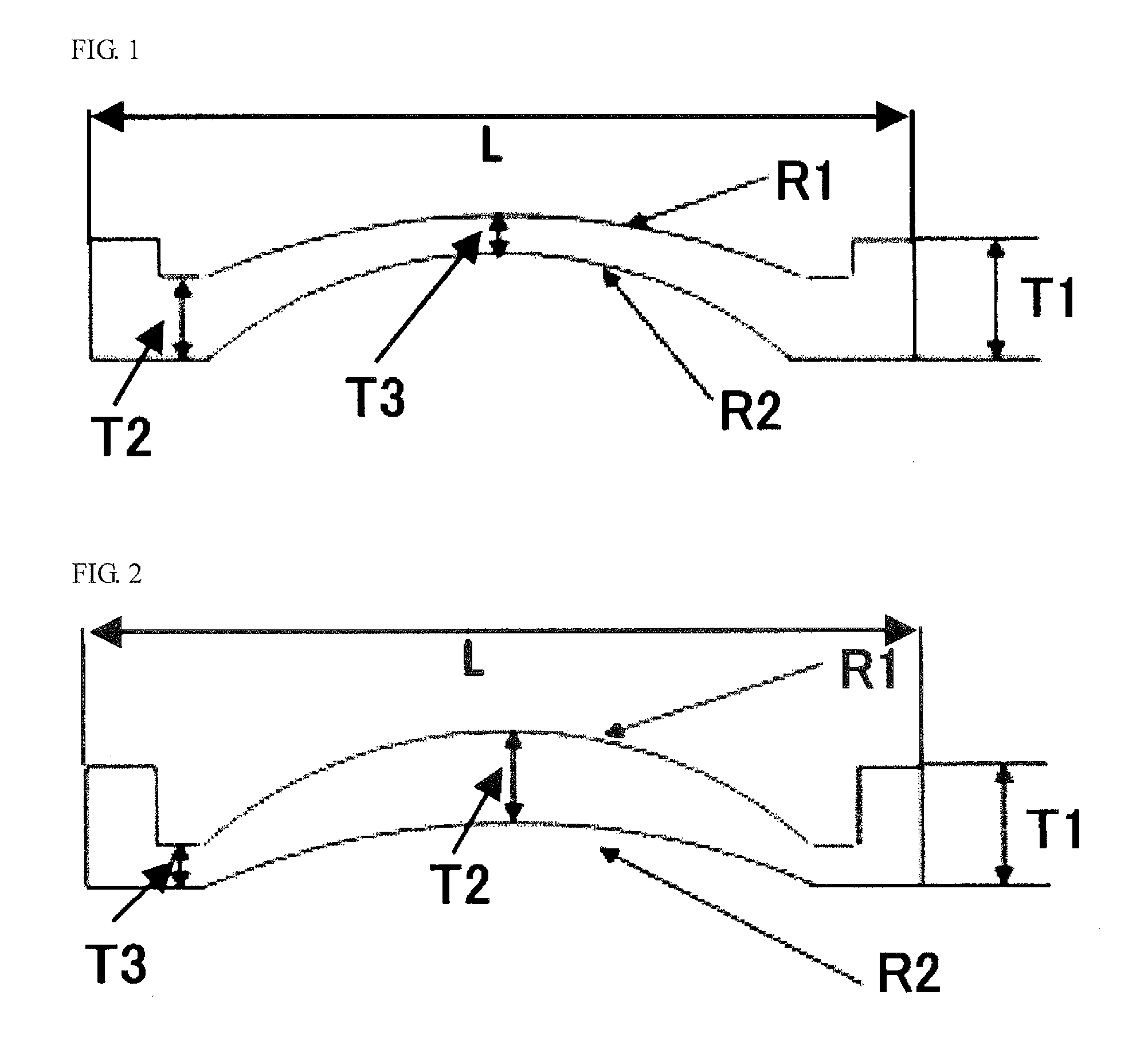
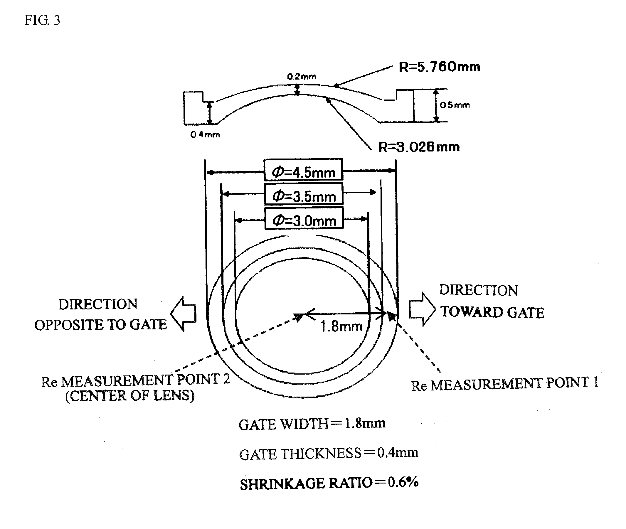
[0117]A thin lens was formed using the resulting pellets. The evaluation results are shown in Table 1.
example 3
[0118]A norbornene-based polymer was obtained in the same manner as in Example 2, except that the amount of 1-hexene was changed to 0.45 parts.
[0119]The conversion ratio of the monomers into a polymer was 99.9%. The resulting norbornene-based polymer had a weight average molecular weight (Mw) of 29,000, a molecular weight distribution (Mw / Mn) of 1.88, a hydrogenation ratio of 99.9%, and a glass transition temperature (Tg) of 145° C.
[0120]A thin lens was formed using the resulting pellets. The evaluation results are shown in Table 1.
PUM
 Abstract
Description
Claims
Application Information
 - R&D
- Intellectual Property
- Life Sciences
- Materials
- Tech Scout
- Unparalleled Data Quality
- Higher Quality Content
- 60% Fewer Hallucinations
Browse by: Latest US Patents, China's latest patents, Technical Efficacy Thesaurus, Application Domain, Technology Topic, Popular Technical Reports.
© 2025 PatSnap. All rights reserved.Legal|Privacy policy|Modern Slavery Act Transparency Statement|Sitemap|About US| Contact US: help@patsnap.com


