System and method for pulsed ground fault detection and localization

a pulsed ground and fault detection technology, applied in the direction of fault location, fault location, conductor type, etc., can solve the problems of large fault current, large fault current, and undesirable condition of ground faul

Inactive Publication Date: 2015-12-03
EATON INTELLIGENT POWER LIMITED
View PDF19 Cites 21 Cited by
  • Summary
  • Abstract
  • Description
  • Claims
  • Application Information

AI Technical Summary

Benefits of technology

The present invention provides a system and method for detecting ground faults in a high resistance grounded power distribution system by monitoring current signals on conductors of the distribution system and identifying a pattern of interest in the current signals over a plurality of cycles to detect a ground fault. The system includes a pulsing circuit and current sensors positioned on each distribution network and at a protective device on each network. The processor associated with each protective device receives the current data from the current sensors and identifies a root mean square (RMS) current from the collected data. The RMS current is analyzed across a plurality of cycles to identify the location of the ground fault in the distribution system. The technical effect of the present invention is the ability to detect and locate ground faults quickly and efficiently in a high resistance grounded power distribution system.

Problems solved by technology

A ground fault is an undesirable condition in an electrical system in which electrical current flows to the ground.
A ground fault happens when the electrical current in a distribution or transmission network leaks outside of its intended flow path.
With solidly grounded systems, the fault currents are large and faulted devices, like motors must be taken off-line immediately.
High transient line-to-ground overvoltages are also a potential issue with ungrounded systems.
This means that very low ground currents may be present in the case of a single fault.
Sensing and locating the ground fault may require highly sensitive devices.
However, suitable ground detection must be provided to alarm (not trip) on this condition and, since the fault current is so low, current monitoring relays may not be effective on ungrounded systems unless they are extremely sensitive (requiring external current transformers).
The ground fault current is limited, but is of high enough magnitude to require its removal from the system as quickly as possible.
The low-resistance grounding arrangement is generally less expensive than the high resistance grounding arrangement but more expensive than a solidly grounded system.
With respect specifically to HRG systems, it is recognized that the use of a hand-held ammeter to trace a high resistance ground fault (HRGF) in power systems does not provide an ideal solution for locating the fault.
While this provides accurate results, such manual positioning of the ammeter at multiple locations, moving from one point to another in the power system until the fault is located, this process is recognized as being time consuming and labor-intensive.
While such a technique does provide for the tracing of a ground fault in a high resistance grounded power system without use of a hand-held ammeter, the technique requires the use of voltage sensors due to the need the extra for sensitivity to differentiate between the capacitive charging current and the actual pulsing ground current, therefore adding cost to the system.
Additionally, the technique is very complex and computationally intensive, while at the same time, certain elements are not robust in being able to detect a fault.

Method used


Image

  • System and method for pulsed ground fault detection and localization
  • System and method for pulsed ground fault detection and localization
  • System and method for pulsed ground fault detection and localization

Examples


Embodiment Construction

[0022]Embodiments of the invention relate to a system and method for detecting and locating HRGFs in a power distribution system and protecting the power distribution system from such ground faults upon detection thereof. The system and method for detecting and locating these HRGFs may be utilized in power distribution systems encompassing a plurality of structures and control schemes, and thus application of the invention is not meant to be limited strictly to power distribution systems having the specific structure described here below.

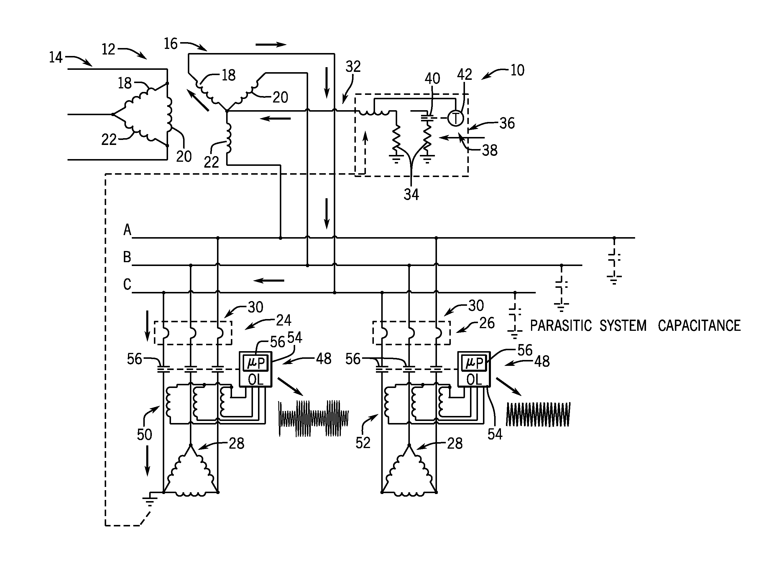
[0023]Referring first to FIG. 1, according to an exemplary embodiment of the invention, a power distribution system 10 is provided with which embodiments of the invention may be implemented. The system 10 includes a power transformer 12 having an input side 14 and an output side 16. The power transformer 12 comprises three phases, i.e., a first phase 18, a second phase 20, and a third phase 22 that are coupled, in the example of FIG. 1, per the angl...


PUM


Abstract

A system for locating a ground fault in a high resistance grounded (HRG) power distribution system includes a pulsing circuit configured to introduce a pulse current into the distribution system and current sensors adapted to monitor three-phase current signals present on conductors of the distribution system, with the current sensors positioned on a number of distribution networks included in the HRG power distribution system and at a protective device included on each respective distribution network. A processor associated with each protective device receives signals from the current sensors for identifying a location of the ground fault in the HRG power distribution system, with the processor associated with each protective device receiving measurements of the three-phase current signals from the current sensors over a plurality of cycles and identifying a pattern of interest in the three-phase current signals across the plurality of cycles in order to detect a ground fault.

Description

BACKGROUND OF THE INVENTION[0001]The present invention relates generally to power distribution systems and, more particularly, to a system and method for detecting and localizing high resistance ground faults in a power distribution system using a pulsed detection algorithm.[0002]A ground fault is an undesirable condition in an electrical system in which electrical current flows to the ground. A ground fault happens when the electrical current in a distribution or transmission network leaks outside of its intended flow path. Distribution and transmission networks are generally protected against faults in such a way that a faulty component or transmission line is automatically disconnected with the aid of an associated circuit breaker.[0003]Various grounding methods may be used for power distribution systems, such that such systems may generally be described as solidly grounded systems, ungrounded systems, high resistance grounded systems, or low resistance grounded systems. With sol...

Claims


Application Information

Patent Timeline
IPC IPC(8): G01R31/08G01R31/02
CPCG01R31/088G01R31/086G01R31/025H02H3/17Y04S10/52
Inventor DIMINO, STEVEN ANDREWLOUCKS, DAVID GLENNWOLFE, ROBERT THOMAS
Owner EATON INTELLIGENT POWER LIMITED
Why Eureka
Try Eureka