Paper transporting device and image forming device
a technology of transporting device and printing device, which is applied in the direction of registering device, thin material processing, printing, etc., can solve the problems of paper curdling after being dried and the quality of printed matter declining
- Summary
- Abstract
- Description
- Claims
- Application Information
AI Technical Summary
Benefits of technology
Problems solved by technology
Method used
Image

Examples
first embodiment
Guide Part in First Embodiment
[0194]Next, the first embodiment of the guide part 66 (guide plate 72) will be described.
[0195]The guide plate 72 illustrated in FIG. 3 is a planar member including the guide surface along a flat surface (plane) on an upper surface side (the side where the chain gripper 64 is arranged), and is arranged along the traveling route of the long side portion on the lower side to be the paper transporting part of the traveling route of the chain 64C of the chain gripper 64.
[0196]By this, the guide surface of the guide plate 72 is arranged as the transporting surface of the paper P in parallel with the paper transporting direction and the paper width direction, to an arrangement side of the chain gripper 64.
[0197]FIG. 8 is a plan view illustrating the upper surface side of the guide plate 72, and FIG. 9 is a sectional view on arrows 9-9 in FIG. 8.
[0198]Also, in these figures, as components of the chain gripper 64, a gripper shaft 120 disposed in the paper width...
second embodiment
Guide Part in Second Embodiment
[0219]Next, the second embodiment of the guide part 66 (guide plate 72) will be described. The guide plate 72 of the guide part 66 in the second embodiment is the one for which a back tension imparting function is added to the guide plate 72 of the guide part 66 in the first embodiment, and has a function of imparting back tension to the paper P transported while the distal end is gripped by the chain gripper 64.
[0220]Since the guide plate 72 in the second embodiment coincides with the guide plate 72 in the first embodiment in the basic configuration, the same signs are attached to components of the actions same as or similar to that in the first embodiment, the description is omitted, and only changes will be described.
[0221]FIG. 12 is a plan view illustrating the guide plate 72 in the second embodiment, and FIG. 13 is a sectional view on arrows 13-13 in FIG. 12.
[0222]As illustrated in the figures, many adsorption holes 140 are perforated in a prescri...
third embodiment
Guide Part in Third Embodiment
[0227]Next, the third embodiment of the guide part 66 will be described. The guide part 66 in the third embodiment illustrates a form of forming the guide surface on a belt surface of an endless belt circulated at the same speed as the transporting speed of the paper P by the chain gripper 64, which is a form using an adsorption belt as the endless belt.
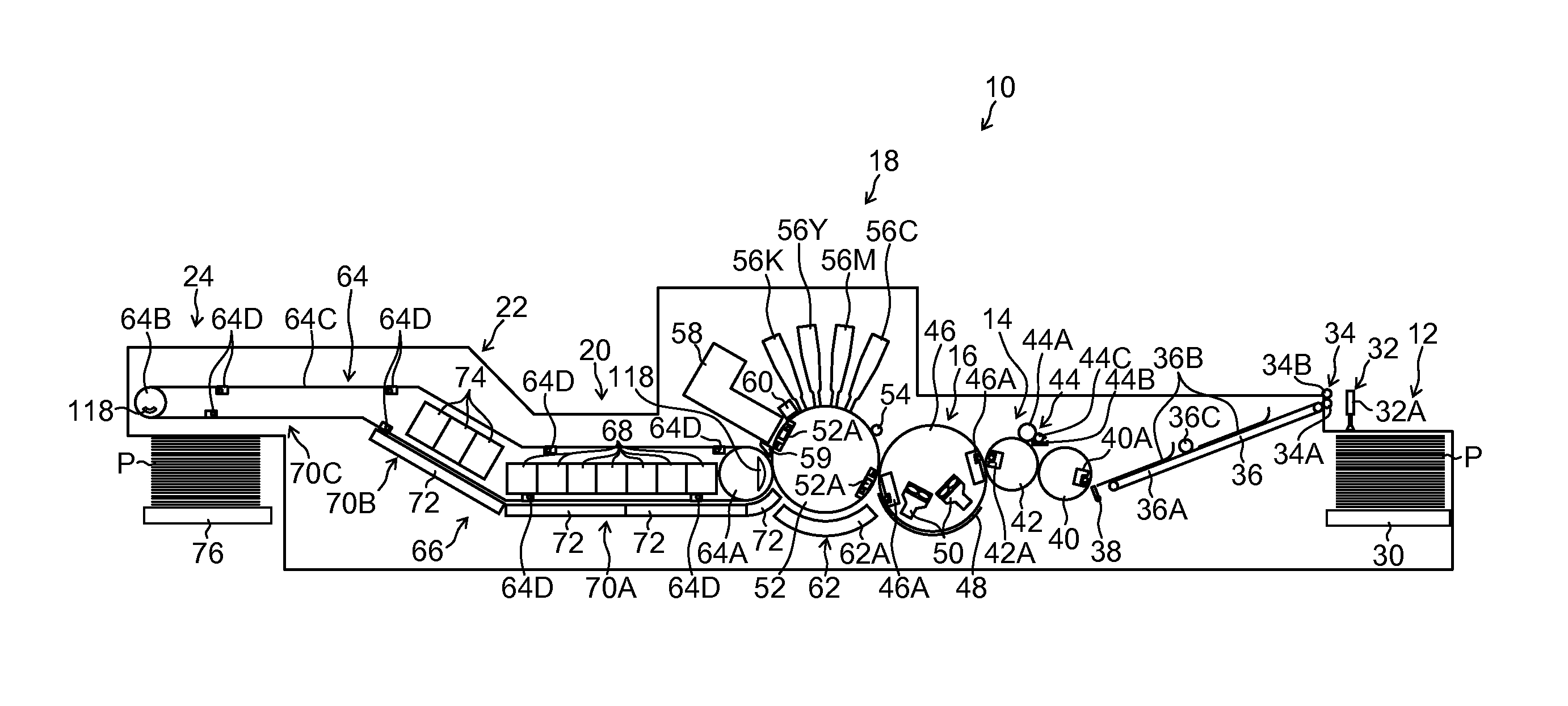
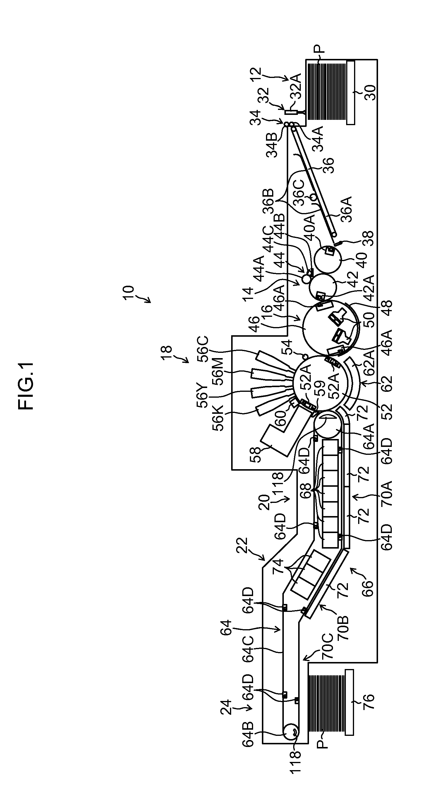
[0228]FIG. 14 is a side view illustrating the guide part 66 in the third embodiment by simplifying the paper transporting mechanism of the ink drying processing part 20, the UV irradiation processing part 22, and the paper discharge part 24, similarly to FIG. 3. The same signs are attached to the components of the same or similar actions as the components in FIG. 3, and the description is omitted.
[0229]In the figure, the guide part 66 includes an endless adsorption belt 150, a driving roller 152, and a driven roller 154.
[0230]The adsorption belt 150 is disposed to the driving roller 152 and the driven ro...
PUM
| Property | Measurement | Unit |
|---|---|---|
| temperature | aaaaa | aaaaa |
| width | aaaaa | aaaaa |
| speed | aaaaa | aaaaa |
Abstract
Description
Claims
Application Information
 - R&D
- Intellectual Property
- Life Sciences
- Materials
- Tech Scout
- Unparalleled Data Quality
- Higher Quality Content
- 60% Fewer Hallucinations
Browse by: Latest US Patents, China's latest patents, Technical Efficacy Thesaurus, Application Domain, Technology Topic, Popular Technical Reports.
© 2025 PatSnap. All rights reserved.Legal|Privacy policy|Modern Slavery Act Transparency Statement|Sitemap|About US| Contact US: help@patsnap.com