
3D push pull chain

a push-pull chain and chain technology, applied in the field of push-pull chains, can solve the problems of affecting the use of push-pull chains requires more space, and the chain can usually transmit traction forces, etc., and achieves the effect of greater storage leeway and flexible us

Active Publication Date: 2015-11-26
IWIS ANTRIEBSSYST
View PDF10 Cites 1 Cited by
  • Summary
  • Abstract
  • Description
  • Claims
  • Application Information

AI Technical Summary

Benefits of technology

The present invention provides a push pull chain that can be used more flexibly and allows for greater storage leeway. The chain can be divided into a driven part and an operational part that can be guided in different directions. This flexibility allows for complex kinematic structures and the implementation of drives that are more compact. The chain can be deflected and guided in two different spatial planes, making it possible to arrange the chain section that interacts with the drive in a space-efficient manner. This enables the installation in a plane that is arranged perpendicularly to the operating direction of a second or further chain section.

Problems solved by technology

Of course, these chains can usually also transmit traction forces.
The use of push pull chains occasionally requires more space especially if the chain is to be rolled up for the purpose of storage or for the drive.
In some cases, this space requirement hampers the use of push pull chains.

Method used


Image

  • 3D push pull chain
  • 3D push pull chain
  • 3D push pull chain

Examples


Embodiment Construction

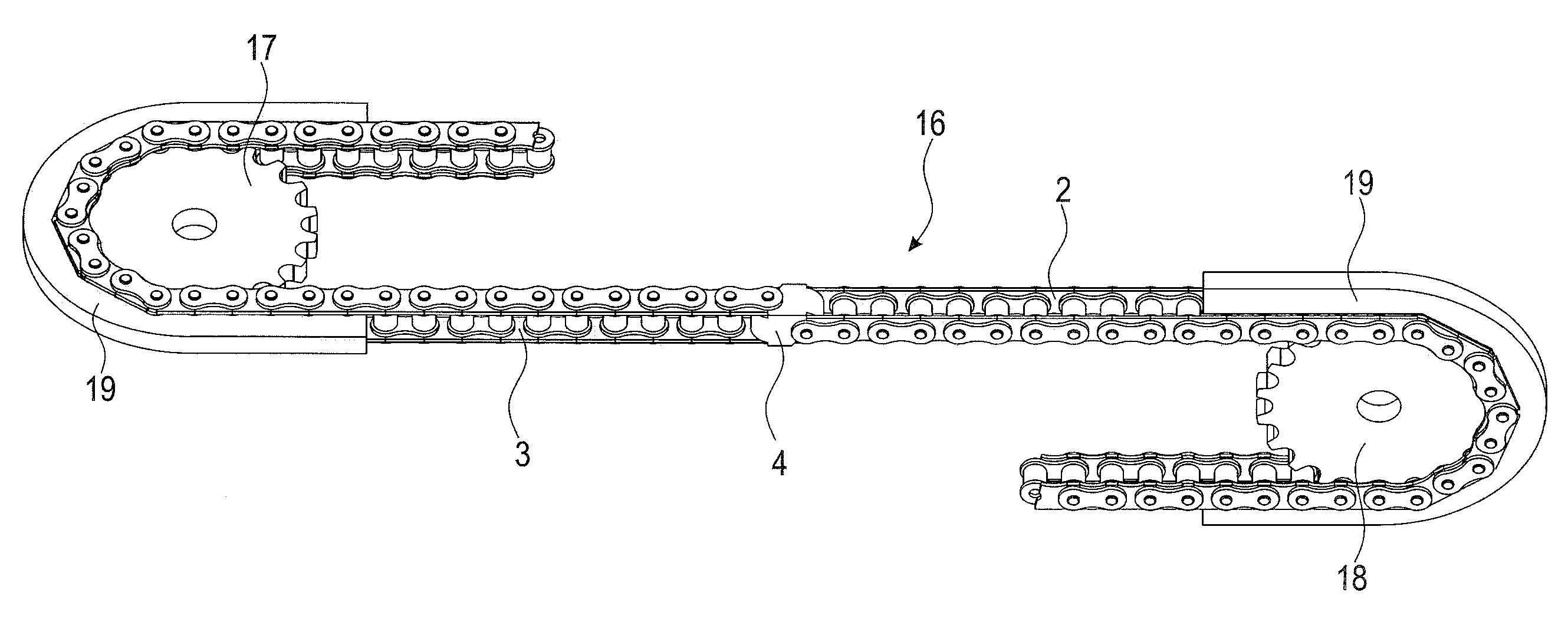
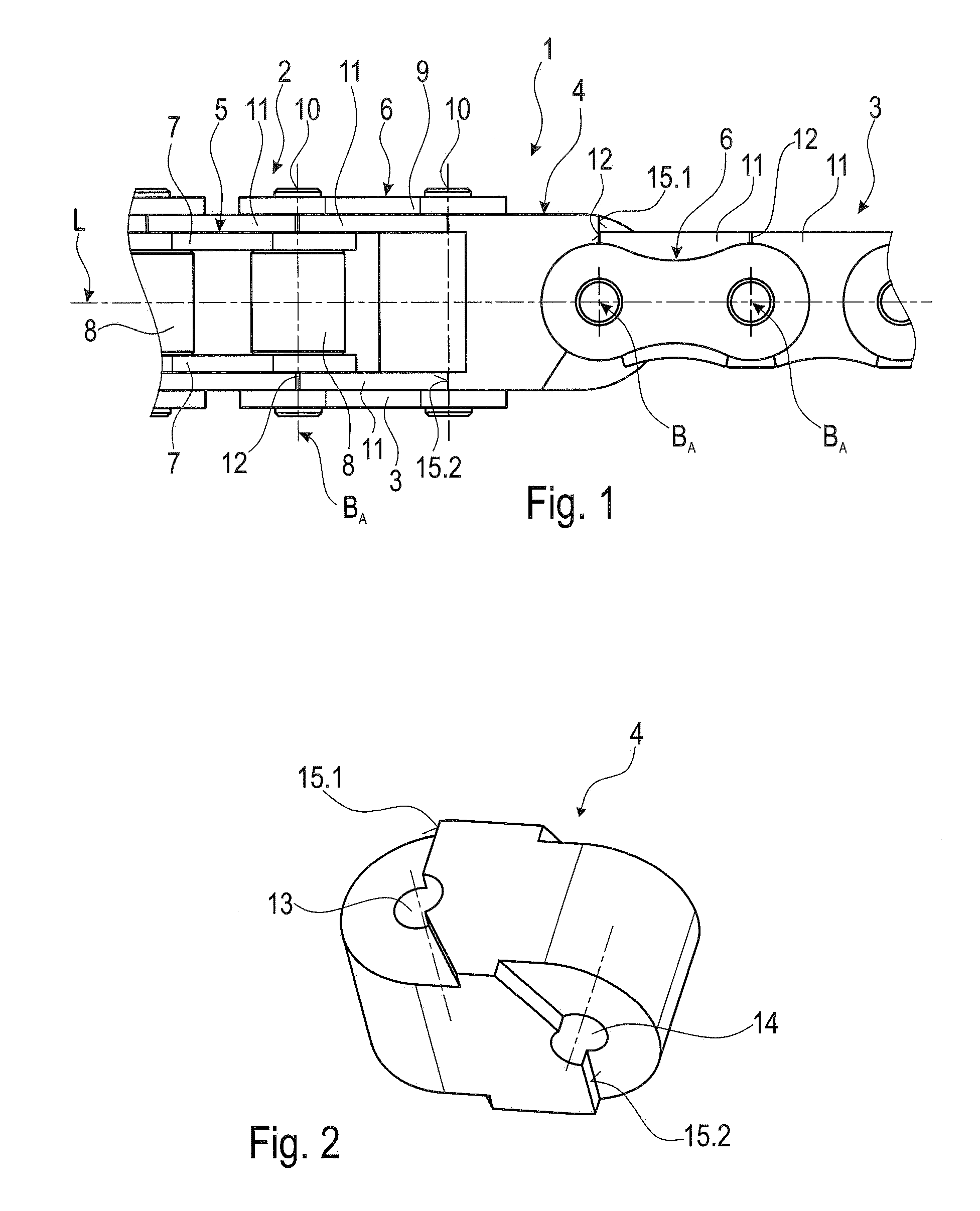
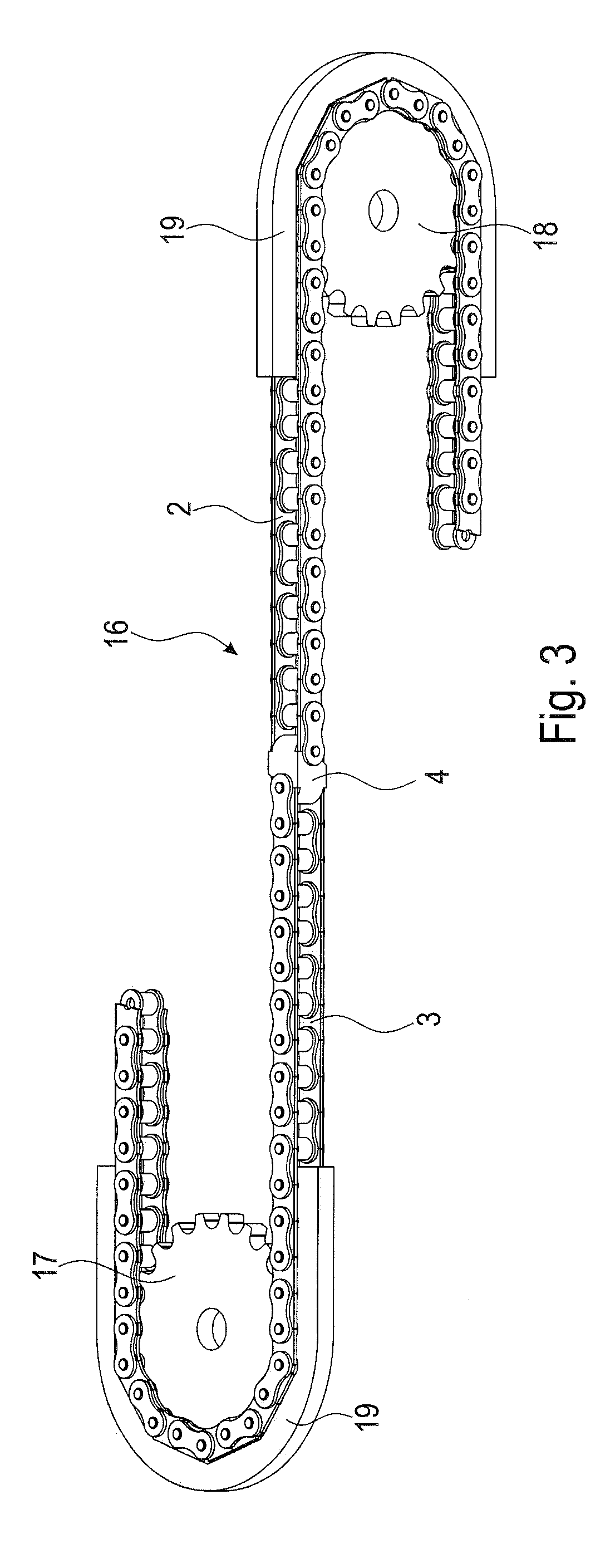
[0024]The push pull chain 1 shown in FIG. 1 comprises a first chain section 2 and a second chain section 3 that are connected to each other in a twisted way around the longitudinal axis L of the push pull chain 1 by means of a linking piece 4 installed in between.

[0025]The first and the second chain section 2 and 3 respectively consist of alternatingly interconnected internal and external chain links 5 and 6.

[0026]Each internal chain link 5 consists of two internal plate links 7 arranged in parallel and two plate links, not shown in the figure, that connect these plate links with each other. A roll 8 is installed rotatably on each of the sleeves.

[0027]Each external chain link 6 consists of external plate links 9 that are arranged in parallel and at a distance to each other and of chain bolts 10, installed in the spacing division of the chain 1, that connect these plate links to each other. Therefore, the chain bolts 10 are pressed into the external plate links 9 in appropriate apert...


PUM


Abstract

A push pull chain is provided with chain links that are connected to each other by respectively one chain joint, designed in a space-efficient manner. The chain joints of a first chain section with their joint axes have a first orientation, whereby the joint axes of the chain joints of a second chain section are arranged in a second orientation that is twisted around the longitudinal axis of the push pull chain or whereby they can be set to this orientation. In addition, a pertaining chain drive is provided.

Description

CROSS-REFERENCE TO RELATED APPLICATION[0001]This application claims priority to foreign European patent application No. EP 14001818.5, filed on May 23, 2014, the disclosure of which is incorporated by reference in its entirety.FIELD OF THE INVENTION[0002]The present invention concerns a push pull chain with chain links that are connected to each other respectively by one chain joint.BACKGROUND[0003]Push pull chains can be found in diverse forms in the state of the art. In most cases, they are plate-link chains with alternating internal and external chain links that are connected by means of a chain joint. The internal and / or external plate links or special stiffening brackets (links) are shaped in a way that the chain can be made bend-proof in one swivel direction of the chain joint. This is ensured for a lineally guided (straight) chain or slightly over-swiveled chain joints so that thrust powers can be subsequently transmitted. The chain joints can still be swiveled in the other s...

Claims


Application Information

Patent Timeline
Patent Type & Authority Applications(United States)
IPC IPC(8): F16H19/06F16G15/00F16G13/07F16G13/20
CPCF16H19/0645F16G13/20Y10T74/20F16G13/07Y10T74/1884F16G15/00F16G15/12
Inventor HARTINGER, GERHARDSAHIN, ORHAN
Owner IWIS ANTRIEBSSYST
Learn More