Electric power tool

a technology of electric power tools and electric power tools, which is applied in the direction of portable power tools, dynamo-electric machines, electrical apparatus, etc., can solve the problems of large electrical components may not be housed in grips, etc., to prevent an increase in the diameter of the grip of electric power tools and prevent deterioration of handling and/or operation of electric power tools

Active Publication Date: 2015-11-12
MAKITA CORP
View PDF3 Cites 11 Cited by
  • Summary
  • Abstract
  • Description
  • Claims
  • Application Information

AI Technical Summary

Benefits of technology

[0007]In view of the above, it is desired to prevent an increase in the diameter of the grip of the electric power tool such that handling and / or operation of the electric power tool may not be deteriorated even when a ferrite core is housed inside the grip.
[0010]In an embodiment, the ferrite core is located such that an axis of the ferrite core is parallel to an axis of the motor or extends along a longitudinal direction of an inner wall surface of the grip. Thus, a housing space for housing the ferrite core may be easily obtained.
[0014]In an embodiment, the motor includes a coil of the stator and a rotor winding that is electrically connected to the coil through a brush and a commutator. Further, an electric wire via which the coil is connected to the brush is passed through the ferrite core. As a result, the ferrite core can be located near the brush, which may be a possible noise source, and / or the commutator, and thus the noise can be effectively and / or greatly reduced.
[0020]In an embodiment, a protrusion is located on an inner wall surface of the cover member such that the ferrite core supported by the support part of the second housing part is pressed by the protrusion from an opposite side of the bottom plate of the support part. As a result, a rattling of the ferrite core can be reduced and eventually the ferrite core may not be easily broken.
[0022]In an embodiment, a capacitor is located between the switch and the controller to reduce noise. Thus, the capacitor can be housed while the diameter of the grip can be minimized as much as possible.

Problems solved by technology

Further, the trigger-type switch may be housed on the grip, but large electrical components may not be housed in the grip.
Thus, handling and / or operation of the electric power tool may be deteriorated.

Method used


Image

  • Electric power tool
  • Electric power tool
  • Electric power tool

Examples


Embodiment Construction

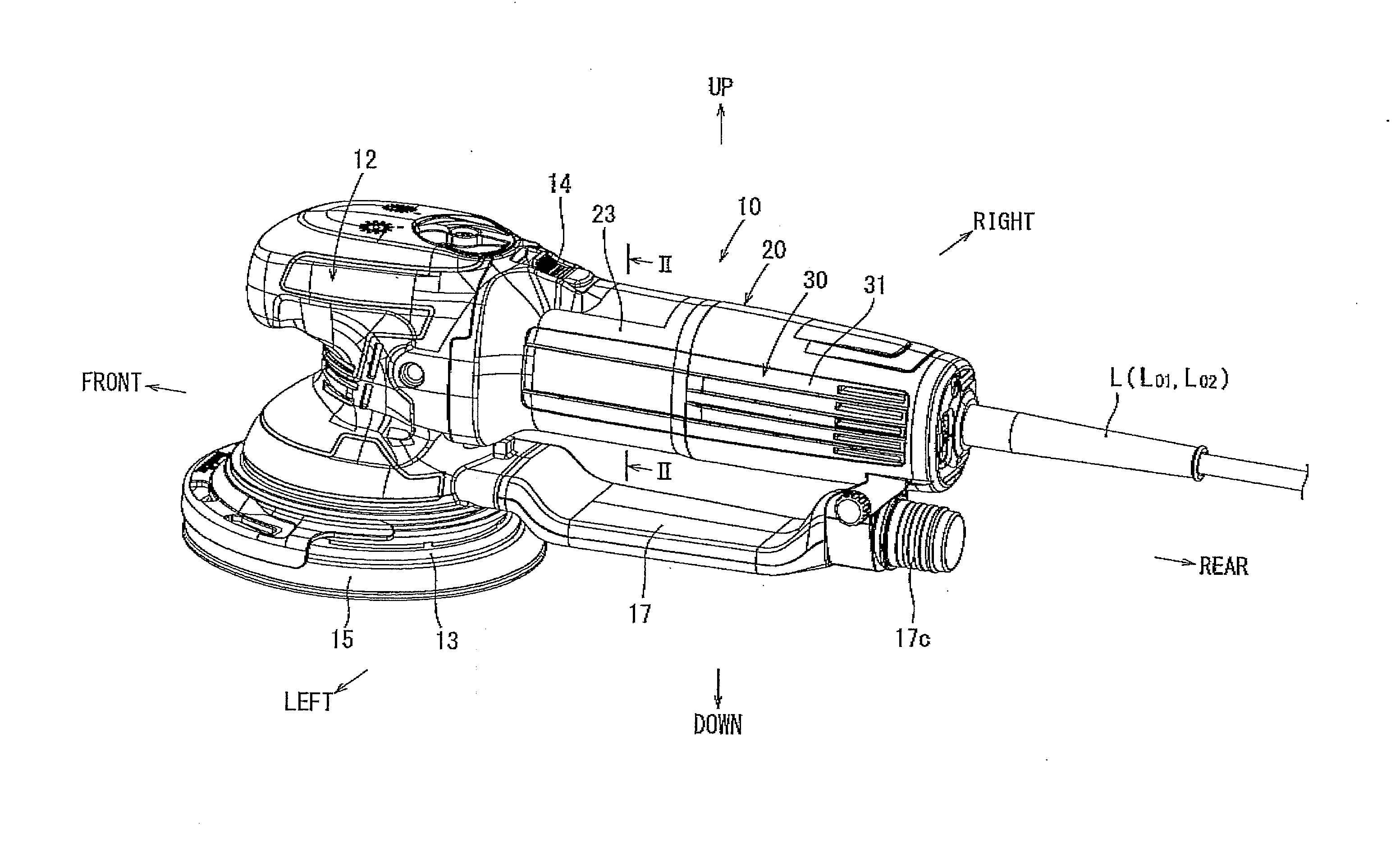
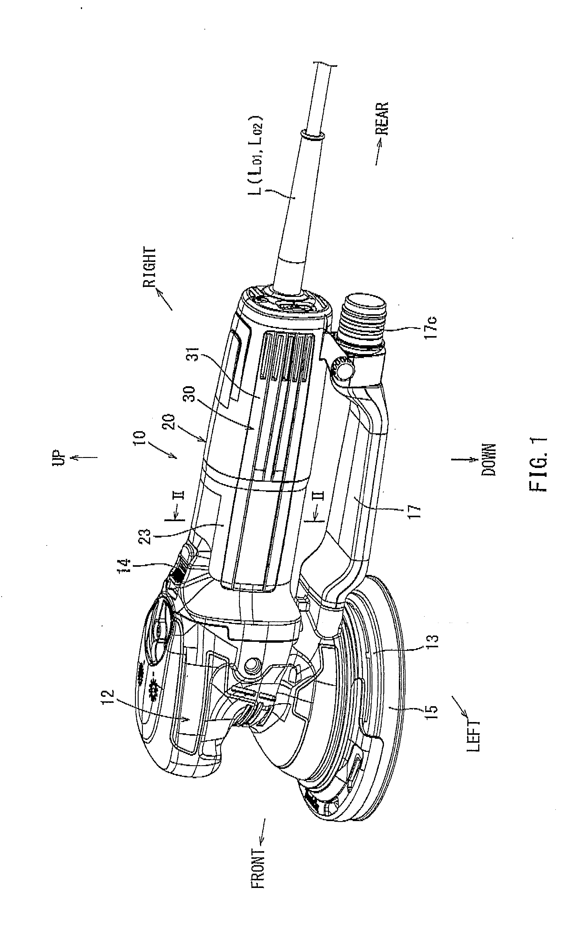
[0037]Referring now to the drawings wherein like numerals refer to like parts, FIGS. 1-12 generally illustrate an electric power tool 10 in accordance with embodiments of the present invention. The electric power tool 10 may be a random orbital sander 10 for polishing wood and / or metal. In detail, the random orbital sander 10 may be configured to polish a material by rotating a disc-shaped polishing disc with eccentric movement. Terms such as “front”, “rear”, “left”, and / or “right” as used in the description below to indicate position, orientation and / or direction may be relative to the position of the random orbital sander.

[0038]As shown in FIG. 1, the random orbital sander 10 may have a celled cylindrical-shaped main housing 12 and a grip 20 protruding backward from an upper side of the main housing 12. Further, the random orbital sander 10 may have a dust-collecting rectangular tube 17 protruding backward from a lower side of the main housing 12. A rear end part of the dust-colle...


PUM


Abstract

In an electric power tool, a stator of a motor is housed in a grip and the stator is located coaxial to the grip. An electric wire for the motor is passed through a ferrite core. Further, the ferrite core is located inside an outer peripheral surface of the stator in a radial direction.

Description

[0001]This application claims priority to Japanese patent application Serial Number 2014-97688, filed on May 9, 2014, the contents of which are incorporated herein by reference in their entirety.BACKGROUND[0002]1. Field[0003]The present invention generally relates to an electric power tool in which a stator of a motor is housed and / or fixed coaxial to a grip. More particularly, embodiments disclosed herein relate to a positioning of a ferrite core used in at electric power tool.[0004]2. Background Art[0005]Japanese Laid-Open Patent Application No. 2011-143499 discloses that a ferrite core is located inside a housing in order to reduce electrical noises generated by electrical components in an electric power tool. The electric power tool disclosed in Japanese Laid-Open Patent Application No. 2011-143499 may have a main housing in which a motor, a speed reduction mechanism, etc., are housed and a grip protruding downward from a lower part of the main housing. The speed reduction mecha...

Claims


Application Information

Patent Timeline
Patent Type & Authority Applications(United States)
IPC IPC(8): H02K11/02H02K7/14
CPCH02K7/145H02K11/02B25F5/02H02K23/66
Inventor HIRATA, YUSUKE
Owner MAKITA CORP
Why Eureka
Try Eureka