Light source module and image projection device
a technology of image projection device and light source module, which is applied in the direction of lighting support device, lighting and heating apparatus, instruments, etc., can solve the problems of low optical efficiency, physical low resolution, and increase the number of pixels on the display surface, so as to improve the resolution and power saving effect of image projection device, the effect of reducing the size and weigh
- Summary
- Abstract
- Description
- Claims
- Application Information
AI Technical Summary
Benefits of technology
Problems solved by technology
Method used
Image


Examples
first embodiment
[0023]In the first embodiment, a light source module is described.
[0024]FIGS. 1A and 1B are structure diagrams showing an embodiment of the light source module, and FIG. 1A is a front view and FIG. 1B is a cross-sectional view. The light source module 1 is formed by a light source unit 11, a light source substrate 12, a light-source drive and control unit 13, and a temperature monitor unit 14. The light source unit 11, the light-source drive and control unit 13, and the temperature monitor unit 14 are mounted on the light source substrate 12. The respective components are described below.
[0025]The light source unit 11 has a structure in which a light emission surface 111 which emits a light of a red wavelength band, a light emission surface 112 which emits a light of a green wavelength band, and a light emission surface 113 which emits a light of a blue wavelength band are stacked, and the stacked light emission surfaces 111, 112, and 113 are held by substrates 114, 115, and 116 mad...
second embodiment
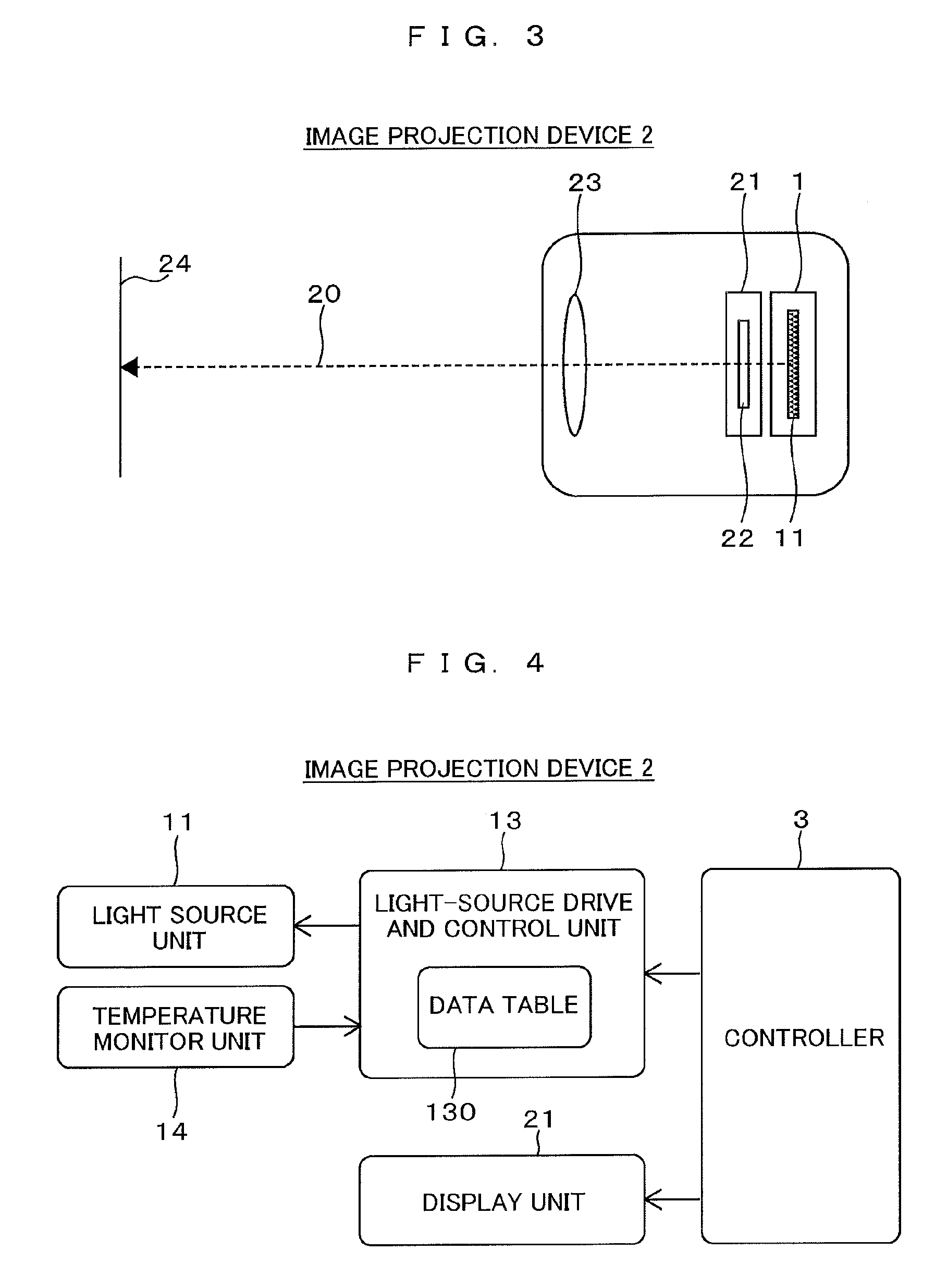
[0034]In the second embodiment, an image projection device using the light source module is described.
[0035]FIG. 3 is a structure diagram showing an exemplary image projection device. The image projection device 2 includes the light source module 1, a display unit 21, and a projection unit 23.
[0036]The light emitted from the light source module 1 is incident on the display unit 21, and an image is generated by a display element 22 in the display unit 21. The image generated by the display element 22 is projected by the projection unit 23 to the outside of the image projection device 2, thereby a projected image 24 is displayed. Please note that broken line 20 shows the traveling direction of a main part of the light for description.
[0037]The display element 22 which generates the image is a transmissive liquid crystal display element in which a liquid crystal element is arranged in every pixel, for example. The liquid crystal elements are sandwiched between polarization filters arra...
third embodiment
[0043]In the third embodiment, an operation of the light-source drive and control unit 13, especially temperature control, is described.
[0044]FIGS. 5A and 5B show an exemplary driving current supplied by the light-source drive and control unit 13 during a normal operation and during temperature control, respectively. The vertical axis represents the driving current I to be supplied to the light source unit 11 while the horizontal axis represents the time t, and a current waveform (control signal) is schematically shown for each emitted light (wavelength band).
[0045]First, an operation during the normal operation shown in FIG. 5A is described. As described before, the light-source drive and control unit 13 employs the field sequential color method. Thus, the light-source drive and control unit 13 causes emission of a light of a wavelength λ1 (e.g., blue), a light of a wavelength λ2 (e.g., green), and a light of a wavelength λ3 (e.g., red) along the time axis. When causing emission of...
PUM
 Abstract
Description
Claims
Application Information
 - R&D
- Intellectual Property
- Life Sciences
- Materials
- Tech Scout
- Unparalleled Data Quality
- Higher Quality Content
- 60% Fewer Hallucinations
Browse by: Latest US Patents, China's latest patents, Technical Efficacy Thesaurus, Application Domain, Technology Topic, Popular Technical Reports.
© 2025 PatSnap. All rights reserved.Legal|Privacy policy|Modern Slavery Act Transparency Statement|Sitemap|About US| Contact US: help@patsnap.com