
Energizing hydrogenerator

Active Publication Date: 2015-10-22
SAFRAN ELECTRONICS & DEFENSE
View PDF16 Cites 6 Cited by
  • Summary
  • Abstract
  • Description
  • Claims
  • Application Information

AI Technical Summary

Benefits of technology

The invention aims to simplify the use of hydrogenerators in systems. It addresses the issue of excessive electricity consumption when the impeller is not rotating at a sufficient speed. The invention provides a solution to avoid this issue.

Problems solved by technology

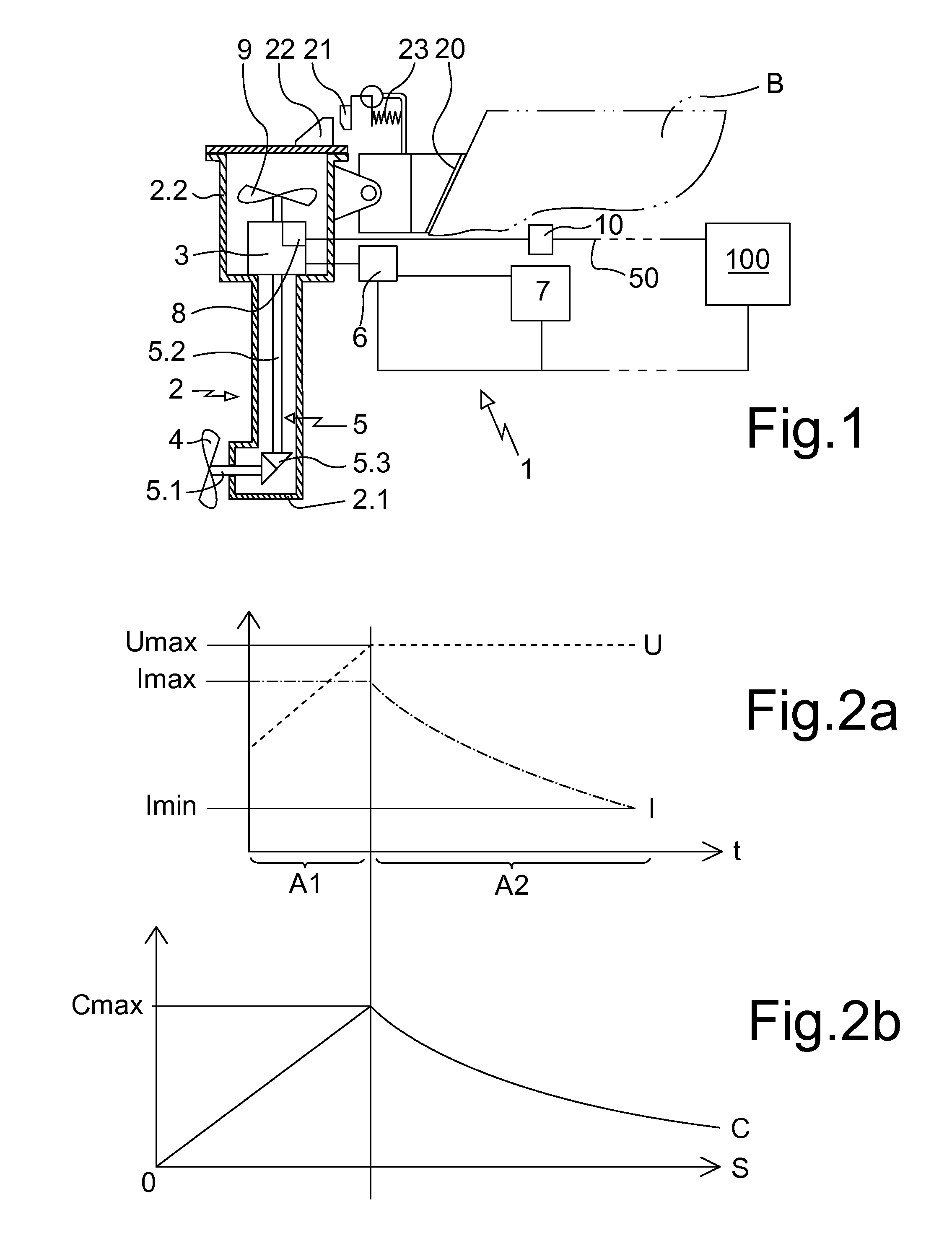
With a constant excitation current, there would be the same drawback as with the constant induction of a permanent-magnet generator, that is to say the resisting torque generated by the generator on the driveshaft would increase as the rotational speed of the impeller increases.

Method used


Image

  • Energizing hydrogenerator
  • Energizing hydrogenerator
  • Energizing hydrogenerator

Examples


Embodiment Construction

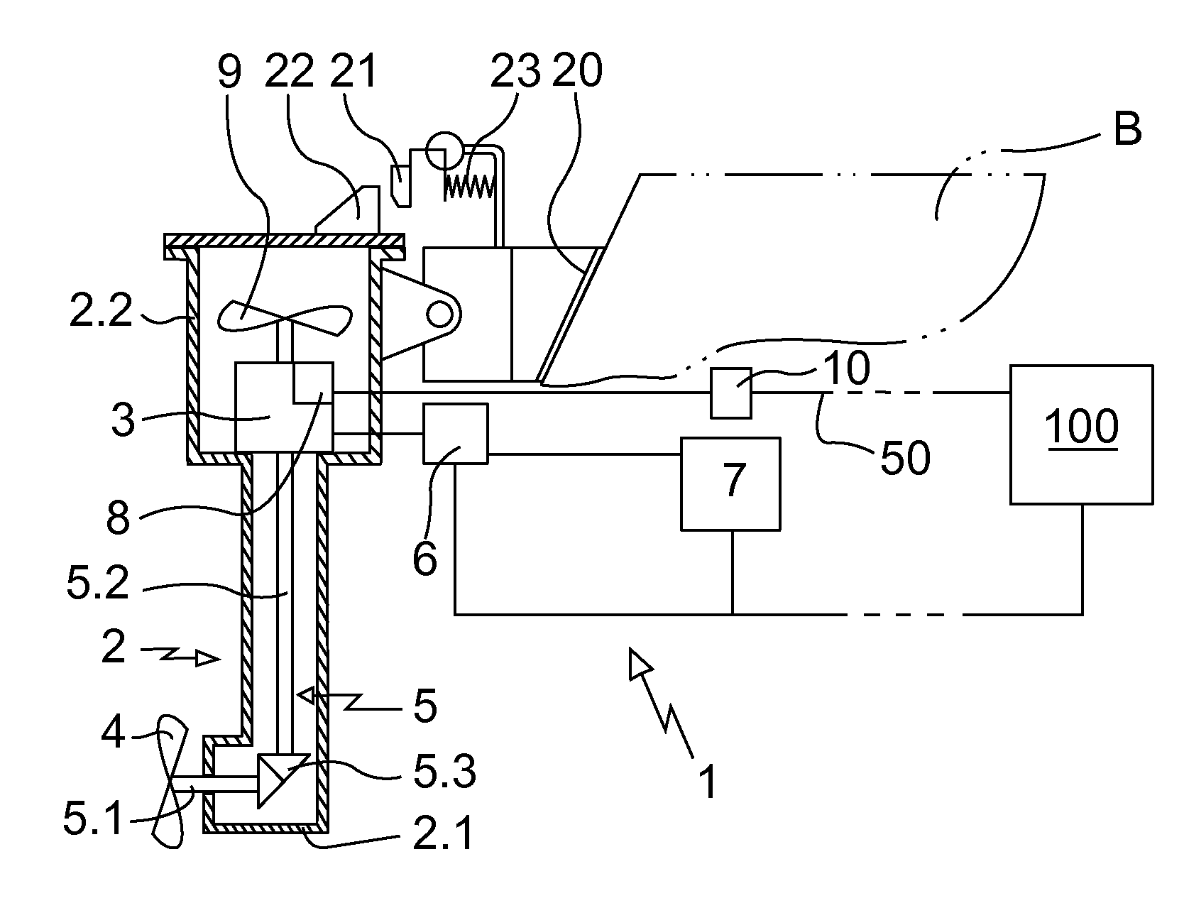
[0022]The on-board assembly for producing and storing electricity comprises at least one hydrogenerator, denoted overall by 1, having an output line 50 connected to batteries of electrical accumulators 100.

[0023]The electrical accumulators 100 are of the Li ion type and have predetermined electrical charging parameters. More precisely, the accumulators 100 accept a charging current with a maximum strength Imax less than or equal to 300 A under a maximum charging voltage Umax of 28.6 V.

[0024]The hydrogenerator 1 comprises a carrying structure 2 on which a generator 3 and a fixed-pitch impeller 4, secured to a shaft of a line of shafts 5.1, 5.2 for driving a rotor of the generator 3 in rotation, are mounted.

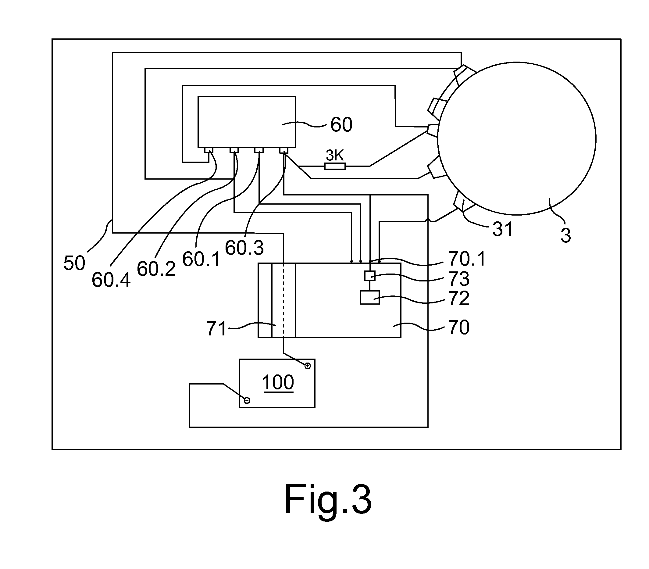
[0025]A rectifier circuit 8 connects the generator 3 to the output line 50. The rectifier circuit 8 is in this case produced directly on the generator 3. Since the hydrogenerator 1 comprises a fan 9 driven by the shaft 5 in order to generate an air flow over the generator 3, so as ...


PUM


Abstract

The invention relates to an on-board assembly for producing and storing electricity, including at least one hydrogenerator having an output line connected to at least one electrical battery having predetermined electrical load parameters. The hydrogenerator includes a load-bearing structure onto which a generator and an impeller, secured to a shaft for driving a rotor of the generator, are mounted. Said assembly is characterized in that the generator is an excitation generator, and the hydrogenerator includes a rectifier circuit, connecting the generator to the output line, and at least one circuit for exciting the generator. The excitation circuit is connected to an excitation current regulator controlled by a control unit set up so that the generator provides a load current consistent with the electrical load parameters on the basis of a resisting torque of the generator, said torque being predetermined so as to limit drag of the impeller.

Description

BACKGROUND OF THE INVENTION[0001]1. Field of the Invention[0002]The present invention relates to an on-board assembly for producing and storing electricity, which can be used in particular on a sailing boat in order, for example, to supply the on-board electronic equipment.[0003]2. Brief Discussion of the Related Art[0004]Such an assembly generally comprises a hydrogenerator having an output line connected to electrical accumulators having predetermined electrical charging parameters. The hydrogenerator comprises a carrying structure on which a generator with permanent magnets and an impeller secured to a driveshaft of a rotor of the generator are mounted, so that the carrying structure can be fastened to the stern of a sailing boat while keeping the impeller submerged. The output of the generator is connected to a rectifier circuit connected to a DC / DC converter connected to the accumulators, in such a way that the hydrogenerator supplies the accumulators with a substantially const...

Claims


Application Information

Patent Timeline
IPC IPC(8): H02J7/14H02J7/00H02P9/30
CPCH02J7/1415H02J7/0057H02P9/305B63J2003/046F03B13/00F03B17/061F05B2240/931Y02E10/30Y02T70/00H02J7/0069Y02E10/20
Inventor NOLLET, MICHEL
Owner SAFRAN ELECTRONICS & DEFENSE
Learn More