
Method and apparatus for modeling of GNSS pseudorange measurements for interpolation, extrapolation, reduction of measurement errors, and data compression

a technology of pseudorange measurement and model, applied in the field of method and apparatus for modeling of gnss pseudorange measurement for interpolation, extrapolation, reduction of measurement errors, data compression, etc., can solve the problems of prohibitive and problematic, loss or interruption of this data stream,

Active Publication Date: 2015-10-22
SUBCARRIER SYST
View PDF1 Cites 3 Cited by
  • Summary
  • Abstract
  • Description
  • Claims
  • Application Information

AI Technical Summary

Benefits of technology

The patent describes an apparatus that uses a processor and computer storage to create a mathematical model of past and future range estimates between two objects. These range estimates are based on the measurement of pseudoranges, which are used to determine the position of an object using satellite signals. The apparatus also includes a data compression method that reduces the amount of data needed to store or transmit the model coefficients. The technical effect of this invention is to improve the accuracy and efficiency of range estimation and positioning systems by using a mathematical model that takes into account the common errors and errors of measurement that are common to both objects.

Problems solved by technology

Loss of, or interruption of, this data stream can in turn be very disruptive to the rover unit.
Such systems suffer from the same RF propagation issues as the GNSS signals and may be blocked or suffer from corrupting effects of multipath on the received signal.
Lower update rates of 5 to 15 seconds are also found, typically due to limits of the transmission technology.
Data rates of 15 kbs or more are required today to convey this information for GPS and GLONASS satellites, and even this can be prohibitive and problematic for various reasons.
The problem addressed herein is to generate and transmit the essential error correction information to the rover devices without using excessive bandwidth or being subject to immediate degrading when loss and corruption of one or more messages in a sequence occurs.

Method used


Image

  • Method and apparatus for modeling of GNSS pseudorange measurements for interpolation, extrapolation, reduction of measurement errors, and data compression
  • Method and apparatus for modeling of GNSS pseudorange measurements for interpolation, extrapolation, reduction of measurement errors, and data compression
  • Method and apparatus for modeling of GNSS pseudorange measurements for interpolation, extrapolation, reduction of measurement errors, and data compression

Examples


Embodiment Construction

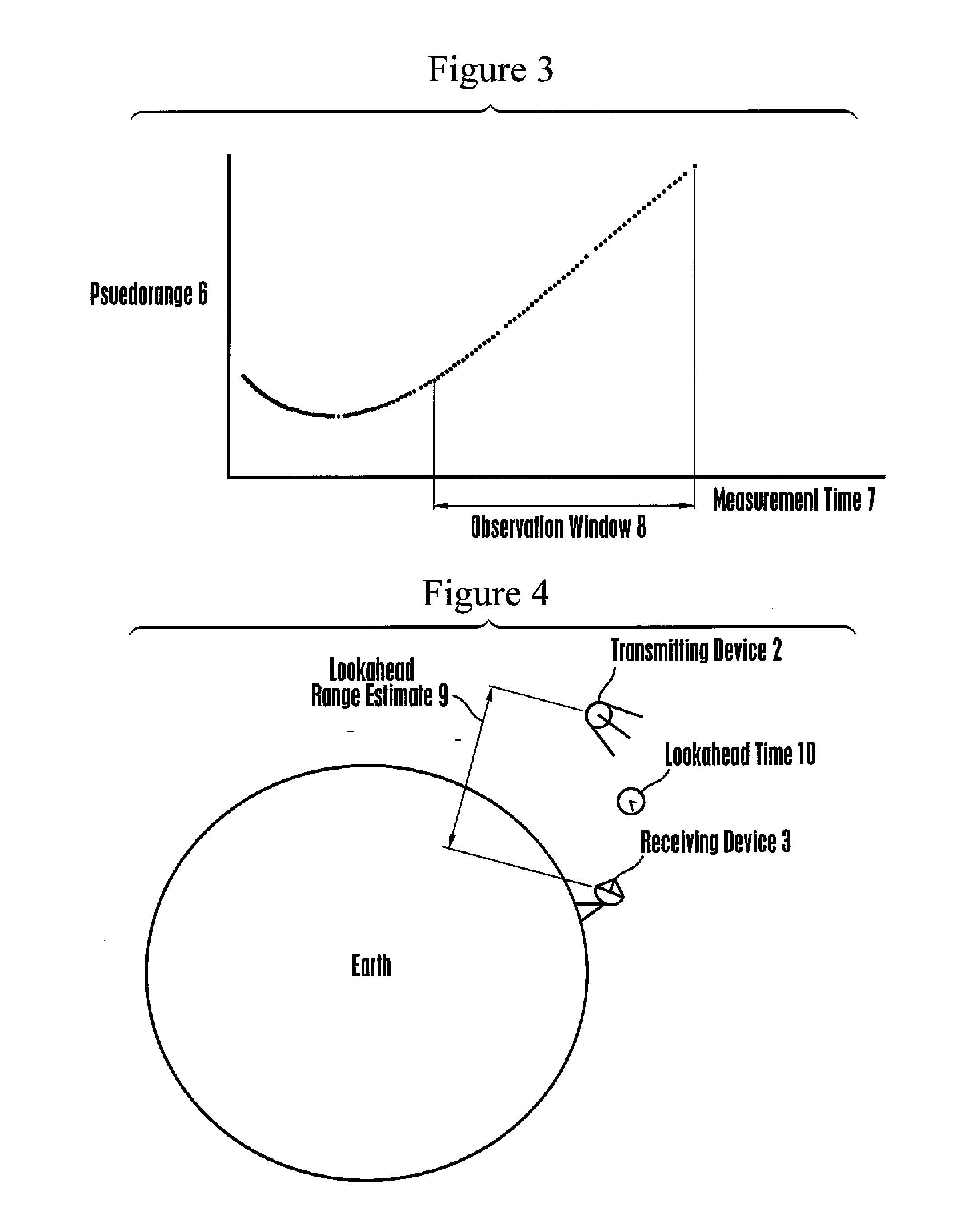
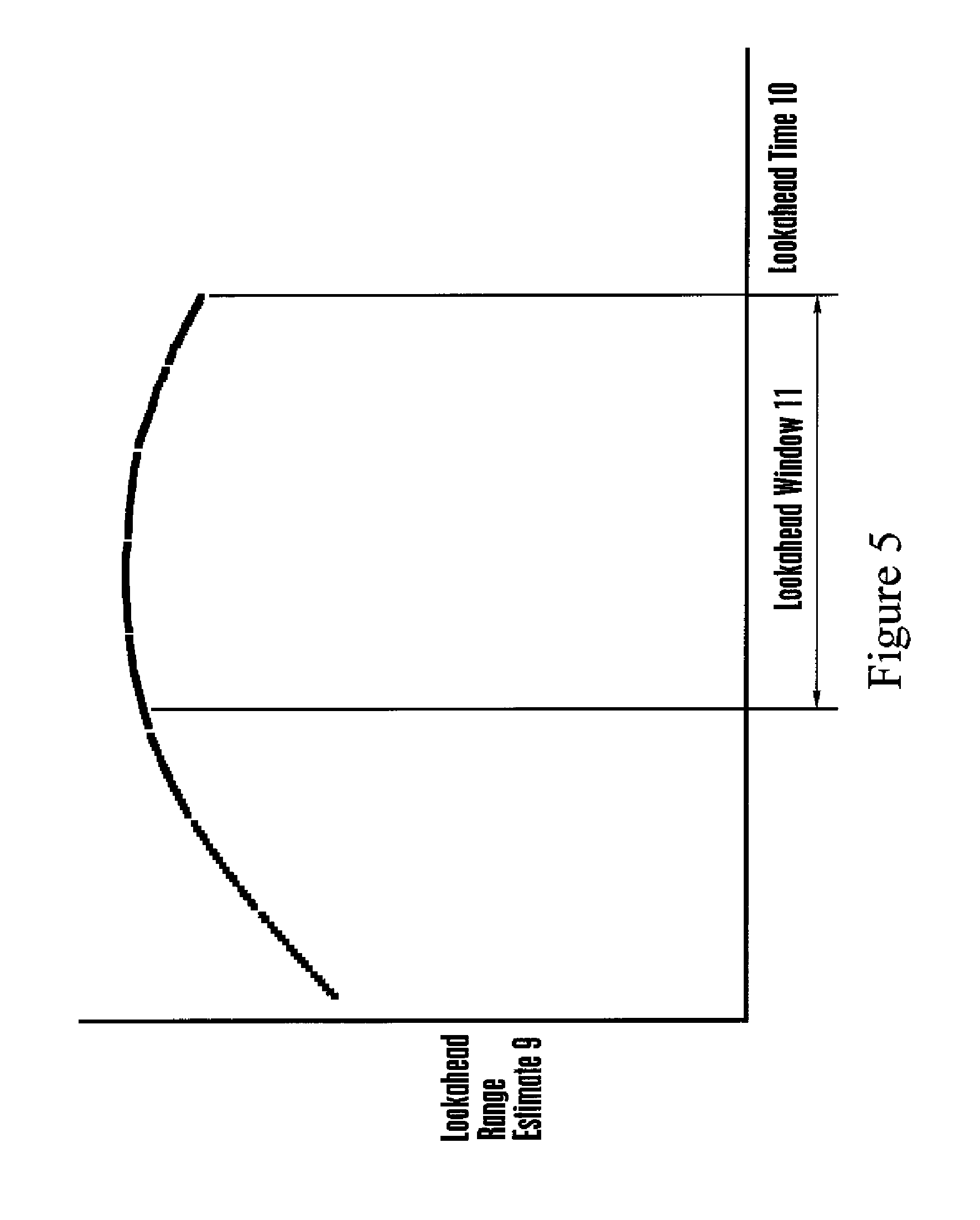
[0039]In brief overview, device built in accordance with present principles is capable of determining or receiving a plurality of measured pseudorange values between an orbiting GNSS satellite and a receiving device at a fixed location on Earth, and associated time values, and of storing the pseudorange and associated time values in a suitable memory device. The preferred embodiment device is further capable of determining or receiving a plurality of estimated range values between the aforementioned GNSS satellite and receiving device at future time values, using ephemeris data broadcast by said GNSS satellite or similar orbital parameters obtained from other sources, and mathematically projected into the future, and of storing the estimated range and associated time values in a suitable memory device. The preferred embodiment device is further capable of computing polynomial regression models describing time histories of ranges between the aforementioned GNSS satellite and receivin...


PUM


Abstract

Polynomial regression models are used to reduce errors in measurements of pseudorange between a GNSS satellite and a receiving station; for data compression by replacing a large number of measurements with a small number of coefficients of the model polynomial, optionally combined with modeling residuals; for extrapolating usefully accurate estimates of future range between the GNSS satellite and the receiving station; and for providing usefully accurate estimates of future coefficient values of the polynomial regression models themselves.

Description

I. FIELD OF THE INVENTION[0001]The present application relates generally to reduction of Differential GNSS message payload by mathematical modeling of pseudorange measurement histories observed at GNSS Reference Stations.II. BACKGROUND OF THE INVENTION[0002]Global Navigation Satellite Systems (GNSS) have grown beyond GPS and GLONASS with the deployment of new designs including the Japanese QZSS, European Galileo, and Chinese COMPASS systems, all of which follow the same fundamental methods of operation and position determination based on RF radio wave ranging techniques. The use and availability of various corrections to aid in the accuracy obtained from a satellite in a GNSS have grown as well.[0003]To improve the accuracy obtainable for positioning and navigation data using a GNSS receiver, various techniques are employed. Some of these involve algorithmic improvements internal to the devices, others involve aiding the device with externally provided information. At a broad level ...

Claims


Application Information

Patent Timeline
IPC IPC(8): G01S19/40
CPCG01S19/40G01S19/41G01S19/072G01S19/04G01S19/43
Inventor BERCHIN, GREGORY JOHNKELLEY, DAVID CHARLES
Owner SUBCARRIER SYST
Learn More