Two stage gasification with dual quench

Active Publication Date: 2015-10-22
LUMMUS TECH INC
View PDF3 Cites 6 Cited by
  • Summary
  • Abstract
  • Description
  • Claims
  • Application Information

AI Technical Summary

Benefits of technology

The patent describes a way to cool down hot gas produced from gasifying carbon. The first step is a chemical quench, where the heat from the first reaction is used to gasify more carbon. The second step occurs after the residual tars produced in the first step have been cracked down to prevent them from causing problems in the process. The technical effect is a more efficient and effective cooling process that reduces the production of toxic emissions and prevents fouling of equipment.

Problems solved by technology

A disadvantage of such two-stage gasification processes is that they often result in a higher level of volatile tar in the raw syngas versus one-stage processes.
However, these units are expensive to build and install and require regular maintenance to manage fouling.
However implementing an immediate water quench is precluded in two-stage gasification systems by the need to remove the residual tars created during pyrolysis of the slurrified feedstock added in the second-stage.
Thermal cracking of these tars requires temperatures above about 1500° F. Additionally, fully water quenching the raw syngas creates contaminated “black water” that requires expensive clean-up processes to prevent pollution of the environment, and often necessitates that the quenched raw syngas be reheated prior to further clean-up and water-gas shifting the syngas to increase hydrogen content.

Method used


Image

  • Two stage gasification with dual quench
  • Two stage gasification with dual quench

Examples


example 1

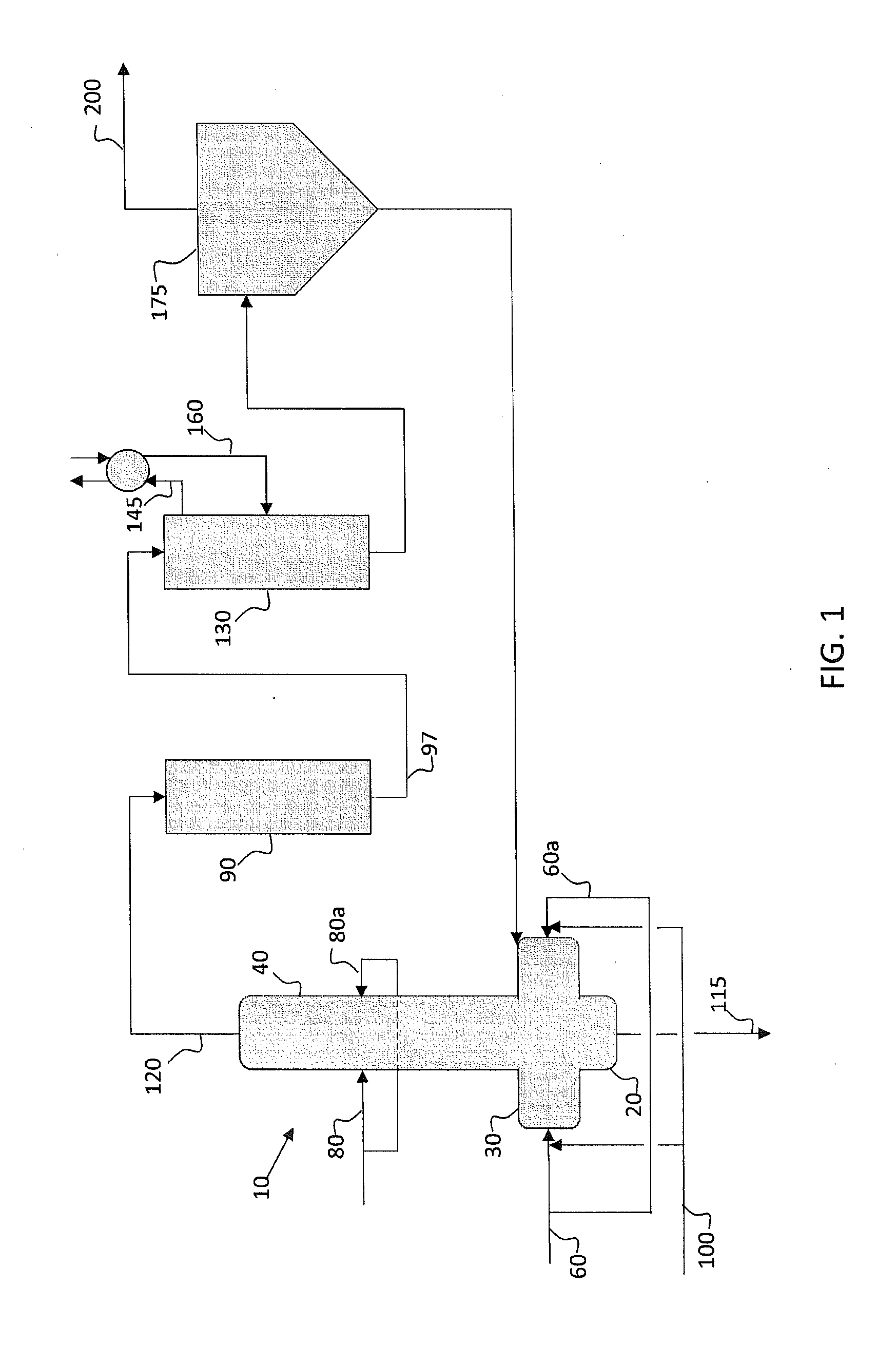
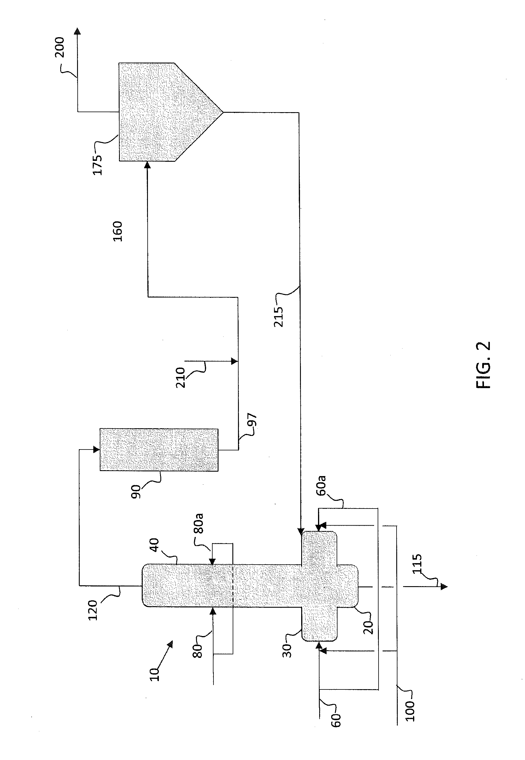
[0040]Detailed computer modeling was performed to assess the effect of implementing the inventive systems and processes on overall operational efficiency and cost. The test case was a two-stage gasifier (as described herein) with a capacity of 6,733 short tons per day of petroleum coke as feedstock. The results of the modeling indicated that overall gasifier performance does not appreciably change, and the raw syngas produced from the gasifier is of very similar composition to that shown in Table 1. In fact, most components differed by less than 1% on a mole basis.

[0041]The major difference detected was in the steam and water balance of the conventional system versus the system of the current disclosure. Implementing the inventive systems described herein with a direct quench of the near-zero tar syngas to a temperature of 1000° F. resulted in the loss of all the saturated high pressure steam that would otherwise have been produced by the HTHRU as it cooled the near-zero-tar syngas....

example 2

[0042]System reliability (i.e., operational availability) is a crucial factor in determining the commercial viability of gasification systems. Therefore, a detailed comparison was conducted between an embodiment of the systems and processes described herein, and a conventional two-stage gasification system utilizing the EGas™ technology (owned by Lummus Technology Inc.) to calculate any effect on system availability. The test case compared two Integrated Gasification Combined Cycle (IGCC) systems, each system comprising two online gasifiers with no back-up. Preventive maintenance is normally performed every 180 days to inspect and maintain the gasifiers. However, conventional IGCC systems that utilize a HTHRU were determined to require more frequent maintenance, on the order of every 90 days. In this hypothetical scenario, the availability of the inventive system designed as disclosed herein was 6.6% greater than the conventional system design.

example 3

[0043]Calculations were performed to determine the economics of implementing the systems and processes described herein. The inventive systems and processes do not require an HTHRU, which is a costly piece of equipment to both build and maintain. A detailed analysis was performed that included the savings in capital expense, expected income tax rate, financial depreciation, and expected inflation rate. The calculated overall savings due to implementing the inventive systems and processes disclosed herein resulted in an internal rate of return of 3.9% over the expected 25 year lifespan of the system.


PUM


Abstract

Improved two-stage entrained-flow gasification systems and processes that reduce the cost and complexity of the design and increase the reliability, while maintaining the efficiency by implementing a first chemical quench followed by a second water quench of the produced syngas. The quenched syngas is maintained above the condensation temperature of at least one condensable component of the syngas, allowing residual particulates to be removed by dry particulate filtration.

Description

FIELD OF THE INVENTION[0001]The present invention relates to a gasification system and process that converts carbonaceous feedstock into desirable gaseous products such as synthesis gas. More specifically, the present disclosure relates to improved systems and processes that reduce the cost and complexity of the design and increase the reliability, while maintaining the efficiency of a two-stage entrained-flow gasification system. This is accomplished by implementing a chemical quench followed by a second quench of the raw syngas.BACKGROUND[0002]The present invention relates to a gasification system and process for converting generally solid feedstock such as carbonaceous material into desirable gaseous products such as synthesis gas. Gasification processes are widely used to convert solid or liquid feedstocks such as coal, petroleum coke and petroleum residue into synthesis gas. Synthesis gas (or syngas) comprises mainly hydrogen gas and carbon monoxide, and is used both for power ...

Claims


Application Information

Patent Timeline
IPC IPC(8): C10J3/72C10J3/46C10J3/84C10K1/04C10K3/00C10K1/02C10K1/00C10J3/48C10K3/04
CPCC10J3/721C10J3/485C10J3/466C10J3/84C10K3/04C10J2300/0943C10K1/024C10K1/005C10K1/04C10J2200/09C10K3/008C10K1/101Y02E20/16Y02E20/18C10K3/003
Inventor KEELER, CLIFTON G.WILLIAMS, CHANCELOR L.BUSTAMANTE, IVAN O.
Owner LUMMUS TECH INC
Why Eureka
Try Eureka