
Modular display system

a display system and modular technology, applied in the field of display systems, can solve the problems of insufficient brightness of projection embodiments, difficulty in achieving a sufficiently bright output, and weight of thousands of pounds when installed,

Inactive Publication Date: 2015-10-15
AD AIR GRP LLC
View PDF3 Cites 5 Cited by
  • Summary
  • Abstract
  • Description
  • Claims
  • Application Information

AI Technical Summary

Benefits of technology

The present invention is a lightweight, flexible planar display system that can be used in inflatable structures, such as balloons. The display system includes a flexible backing with a conductor and a controller, and a plurality of light components on a flexible substrate, such as RGB light elements. The display can be affixed to the inflatable structure using a flexible mesh backing or a plastic mesh covering the outer surface of the inflatable structure. The system also includes a retaining device at a lower point of the display. The inflatable structure can have internal tension lines or a convex shape, and can have a payload fastener for attaching a camera system or a sensor system. The computer system can receive and store captured images from the camera system or the sensor system. The technical effects of the invention include a lightweight, flexible display system that can be easily attached to inflatable structures and a variety of applications using the same inflatable structure.

Problems solved by technology

Screens formed from light emitting diodes (LED) can produce bright output, but weigh thousands of pounds when installed in the sizes need for larger crowds.
Some technical developments with this approach often address the challenge of distortion caused by the curvature of the projection screen.
However, an additional challenge of using conventional projectors in outside events is the difficulty in achieving a sufficiently bright output.
Projection embodiments are generally insufficiently bright for exterior, daytime use.
In addition, conventional high powered projectors introduce considerable weight.
Further, it is difficult to view projected images at extreme angles.

Method used


Image

  • Modular display system
  • Modular display system
  • Modular display system

Examples


Embodiment Construction

1. Introduction

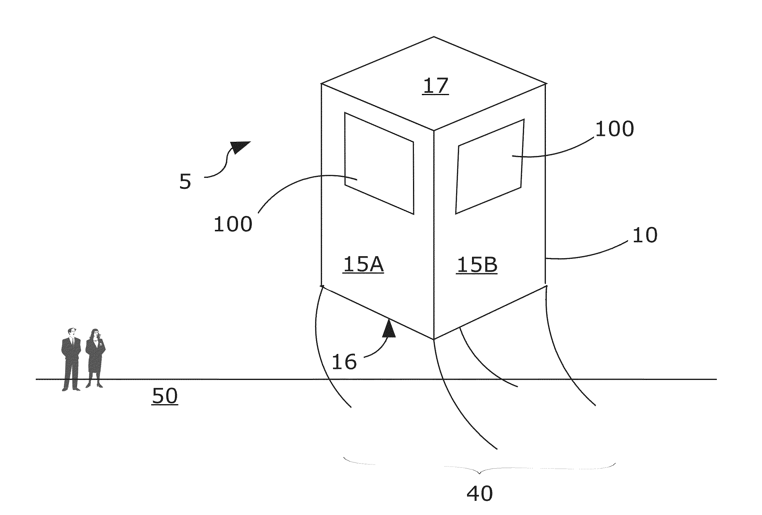
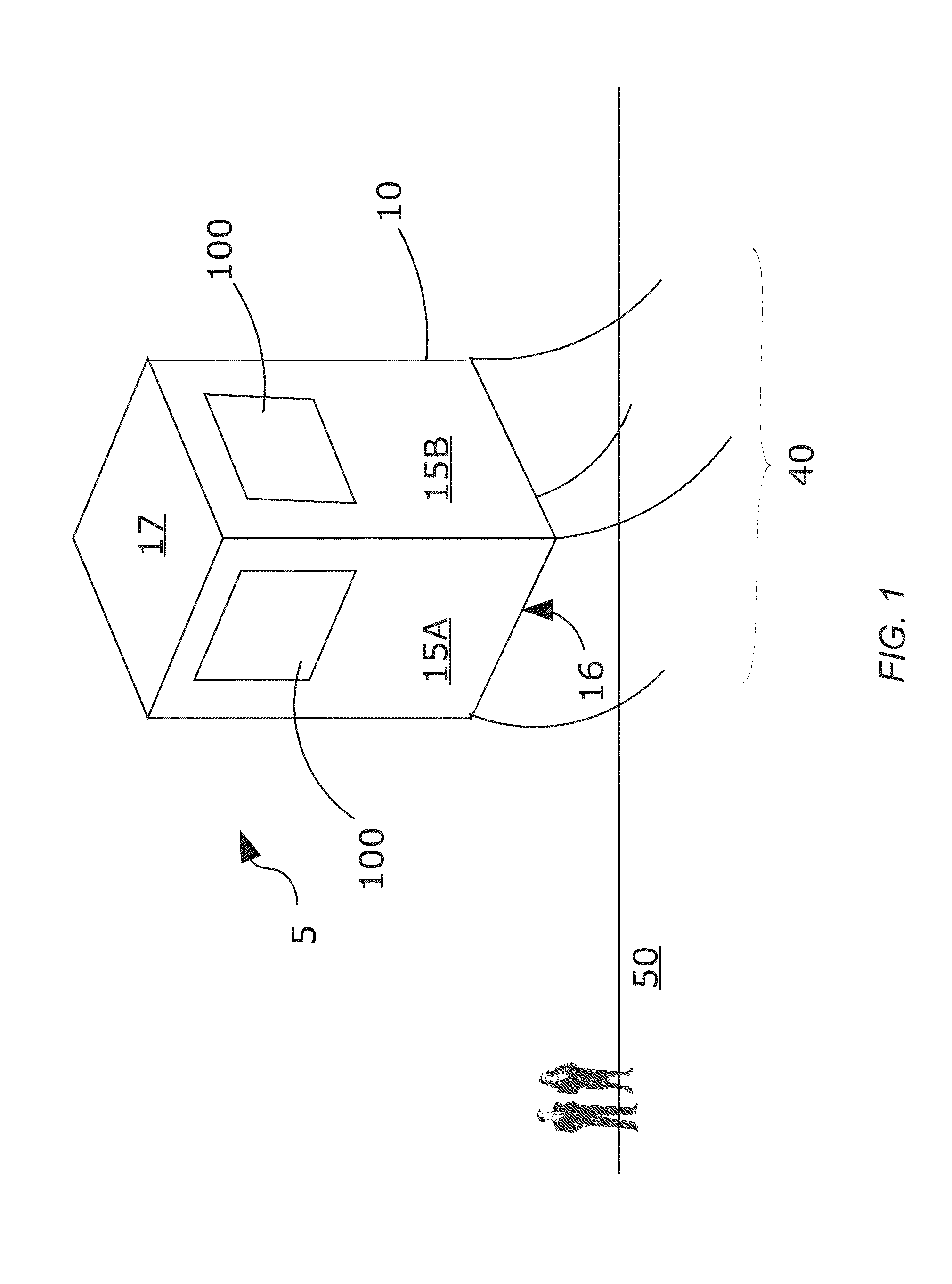
[0051]Turning now to the figures, FIGS. 1-22 illustrate certain aspects of various exemplary embodiments of the inflatable, variable-buoyancy, modular display system, also called “system”, according to the present approach. In illustrative, non-limiting embodiments, the system may include an inflatable structure that is scalable to allow large displays to be used for maximum exposure to potential viewers. Large crowds require large screens, elevated above the crowd.

[0052]The development of such a system 5 has involved the development of new elements, including as illustrated in FIG. 1, new inflatable structures 10 and a new, lightweight flexible planar display 100. Embodiments of display 100 disclosed herein are lighter in weight than conventional displays, suiting them for use with the inflatable structure 10 of system 5. In addition, inflatable structures 10 are sufficiently robust and adapted for elevation of displays 100 to an altitude that permits view by spectat...


PUM


Abstract

An inflatable, variable-buoyancy, modular display system having an inflatable structure with one or more light weight, high definition displays affixed or attached to one or more surfaces of the inflatable structure. The inflatable structure may be used to elevate the displays for viewing by larger numbers of people, as for festivals or sporting events. The display or displays may alternatively be imbedded within at least a portion of the structure. In still other forms, the structure may comprise a material that is capable of producing a display or displays. Also included is a modular display of flexible, light weight design. The display omits conventional display cabinets and features an open design, thereby offering flexibility and a lighter weight appropriate for such systems.

Description

CROSS-REFERENCE TO RELATED APPLICATIONS[0001]This application claims the benefit of U.S. Provisional Application No. 61 / 970,433 filed on Mar. 26, 2014, which is hereby incorporated in its entirety.STATEMENT REGARDING FEDERALLY SPONSORED RESEARCH OR DEVELOPMENT[0002]Not ApplicablePROGRAM LISTING COMPACT DISC APPENDIX[0003]Not Applicable,NOTICE OF COPYRIGHTED MATERIAL[0004]The disclosure of this patent document contains material that is subject to copyright protection. The copyright owner has no objection to the reproduction by anyone of the patent document or the patent disclosure, as it appears in the Patent and Trademark Office patent file or records, but otherwise reserves all copyright rights whatsoever. Unless otherwise noted, the applicant owns all trademarks and service marks identified herein.BACKGROUND[0005]1. Field of the Invention[0006]The present disclosure relates generally to the field of display systems. More specifically, the present invention relates to inflatable, v...

Claims


Application Information

Patent Timeline
IPC IPC(8): H04N7/015H04N1/21G06F1/16H04N7/18G09G5/00G06T1/20
CPCH04N7/015G09G5/00G06T1/20G06F1/1649G09G2300/04G06F1/1652H04N7/183H04N1/2112G09G2370/00G06F1/166G09F27/00H04N5/64H04N7/002H04N7/18G09F27/005G09F9/3026G09F9/33G09F21/20G09F2027/002B63B7/08B63B35/58B63B22/00
Inventor FACCHINETTI, ANDREAFITZGERALD, ROBERT T.WILLMONT, JAYCOSTELLO, ANGELA W.TEHINI, JARYD M.MAGRAW, FORREST J.
Owner AD AIR GRP LLC
Learn More