
Display apparatus and illumination unit

a technology of display apparatus and illumination unit, which is applied in the direction of instruments, static indicating devices, lenses, etc., can solve the problems of display luminance drop, and achieve the effect of high luminance and increased ligh

Active Publication Date: 2015-10-15
SONY CORP
View PDF13 Cites 46 Cited by
  • Summary
  • Abstract
  • Description
  • Claims
  • Application Information

AI Technical Summary

Benefits of technology

The illumination unit and display apparatus described in this patent make it possible to switch between 3D and 2D displays without using physical barriers or polarizers. They also increase the amount of light that enters the display at a suitable viewing angle, resulting in a brighter display.

Problems solved by technology

This has caused an issue that light is absorbed by the polarizer, which results in decrease in display luminance.

Method used


Image

  • Display apparatus and illumination unit
  • Display apparatus and illumination unit
  • Display apparatus and illumination unit

Examples


first embodiment

2. Modification of First Embodiment

[0239][Modification 1]

[0240]In the above-described embodiment, description is provided, as an example, of the case where each of the linear electrodes 32D extend in the direction parallel to the light entering surface 10A. However, as illustrated in FIG. 27, for example, each of the linear electrodes 32D may extend in a direction obliquely intersecting with the light entering surface 10A while the partial electrodes 32A have a layout same as that in the above-described embodiment. At this time, in a case where P2=P1 / N and P4=P3 are established, as illustrated in FIG. 28A, the respective convex portions 50A may be preferably arranged so that each of the convex portions 50A corresponds to one of the partial electrodes 32A in a one-to-one relationship, and may be more preferably so that each of the convex portions 50A is opposed to one of the partial electrodes 32A, for example. It is to be noted that each of the convex portions 50A has a rectangular ...

second embodiment

4. Modifications of Second Embodiment

[0368][Modification 1]

[0369]In the second embodiment described above, the lens sheet 50 may be fixed onto the polarizing plate 210B with the use of a gluing agent or an adhesive. At this time, as illustrated in FIG. 99, the flat surface of the lens sheet 50 may be preferably fixed onto the polarizing plate 210B with a fixing layer 212 made of a gluing agent or an adhesive in between, for example. Moreover, in a case where the convex portions 50A are formed by solidifying an energy-curable resin such as a UV-curable resin, the convex portions 50A may be formed directly on the surface of the polarizing plate 210B as illustrated in FIG. 100, for example.

[0370][Modification 2]

[0371]In the second embodiment and the modification thereof described above, as illustrated in FIGS. 101 and 102, a parallax bather 80 may be provided on the light exiting side of the backlight 211, for example. As illustrated in FIG. 101, the parallax bather 80 may be preferabl...


PUM

PropertyMeasurementUnit
temperatureaaaaaaaaaa
refractive indexaaaaaaaaaa

Abstract

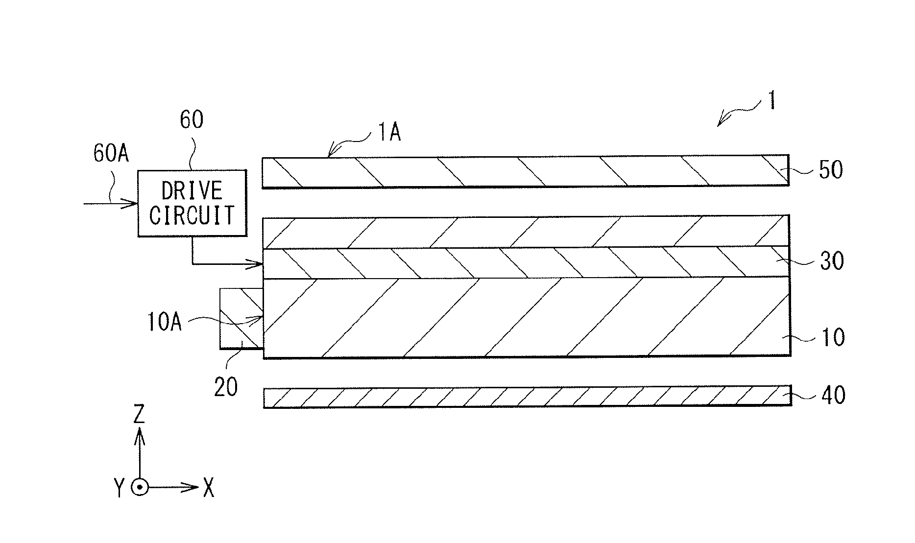
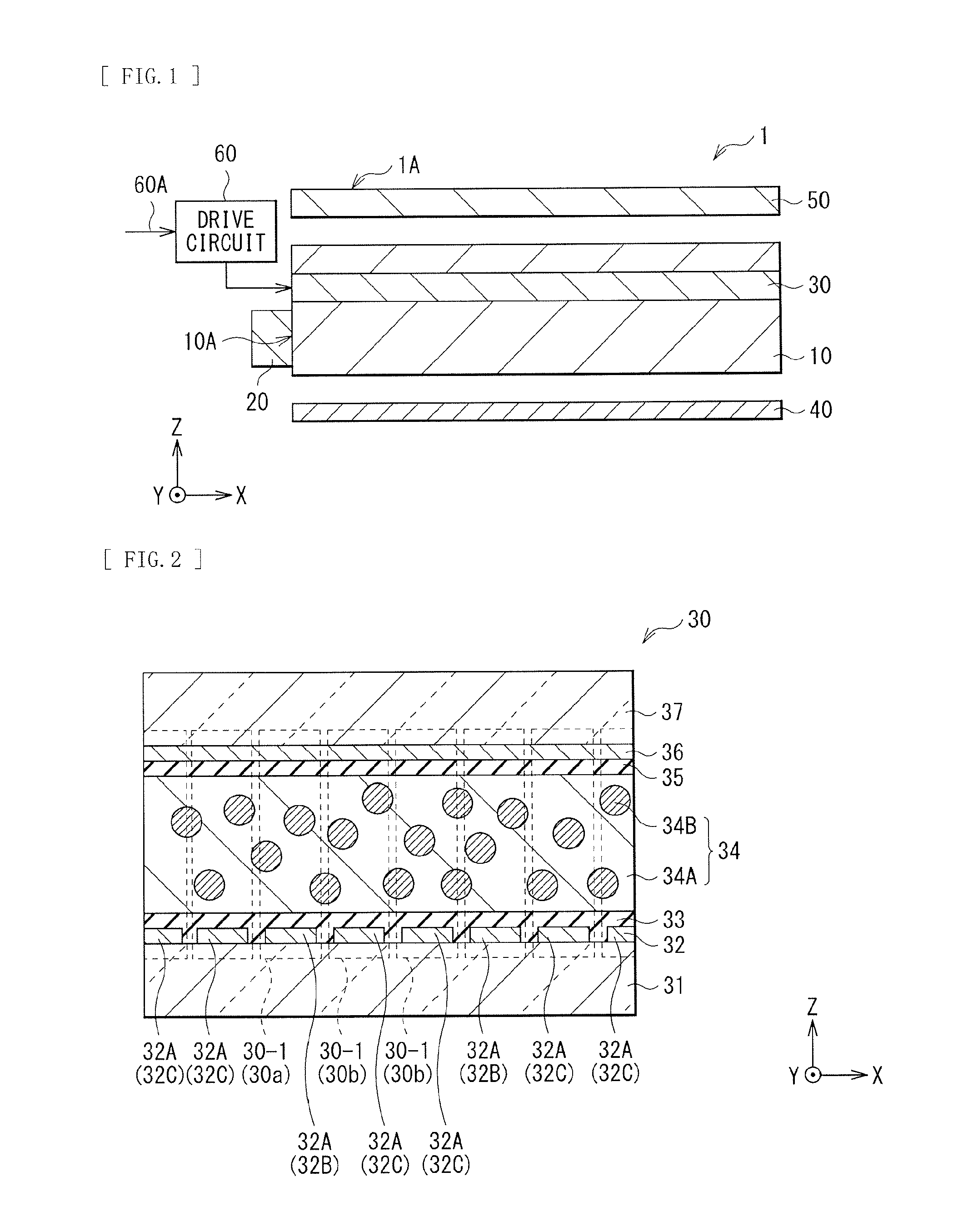
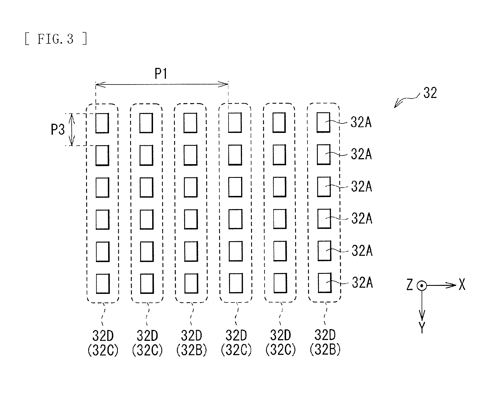
An illumination unit of an embodiment of the present technology includes: an illumination optical system configured to generate illumination light; and a plurality of lenses configured to reduce a divergence angle of the illumination light. The illumination optical system includes: a light source (20) configured to apply light onto an end surface of one of a first substrate and a second substrate; and a light modulation layer (30) provided in a gap between the first substrate and the second substrate. The illumination optical system includes an electrode configured to generate an electric filed that generates, in the light modulation layer (30), a plurality of linear scattering regions (30B) in a three-dimensional mode, and to generate an electric field that generates, in the light modulation layer, a planar scattering region in a two-dimensional display mode. The lenses are arranged side by side in a direction in which the linear scattering regions extend, and are also arranged side by side in a direction intersecting with the direction in which the linear scattering regions extend.

Description

TECHNICAL FIELD[0001]The present technology relates to a display apparatus that is capable of performing two-dimensional display (planar display) and three-dimensional display (stereoscopic display), and to an illumination unit suitably applicable as a backlight of such a display apparatus.BACKGROUND ART[0002]Some display apparatuses capable of performing three-dimensional display require to wear eyeglasses dedicated therefor, and the others require no eyeglasses dedicated therefor. The latter display apparatuses use a lenticular lens, a parallax barrier, etc. in order to allow a stereoscopic picture to be perceived with naked eyes. Picture information is thus distributed to left and right eyes, and different pictures are thereby viewed between the left and right eyes. As a result, three-dimensional display is achieved.[0003]By the way, in a case where a physical barrier is provided in the display apparatus that is capable of allowing a stereoscopic picture to be perceived with nake...

Claims


Application Information

Patent Timeline
Patent Type & Authority Applications(United States)
IPC IPC(8): G02F1/1335G09G3/34G09G3/36G09G3/00G02B30/27G02B30/30H04N13/305H04N13/307
CPCG02F1/133526G09G3/003G09G3/3406G02F1/1336G02F1/133504G02F1/133528G09G3/36H04N13/305H04N13/317H04N13/307H04N13/31H04N13/312H04N13/359H04N13/324G02B6/0038G02B6/0046G02B6/0068G02B6/0071G02B6/0061G02F1/1334G02B30/27G02F1/133626G02B3/0043G02B3/005G02F1/13476G02F1/133606G02F1/133607G02B30/30
Inventor SHINKAI, SHOGOEBISUI, AKIRA
Owner SONY CORP
Learn More