
3C Smart Ring

Inactive Publication Date: 2015-10-08
WHYNOT TECH
View PDF4 Cites 19 Cited by
  • Summary
  • Abstract
  • Description
  • Claims
  • Application Information

AI Technical Summary

Benefits of technology

The present invention provides a 3C smart ring that can be integrated with user's portable 3C electronic products in a cable or wireless coupling manner. The 3C smart ring can transmit user's speech to the 3C products and transform it into corresponding wording through a built-in speech recognition system. This improves input efficiency and replaces the current screen keyboard. The 3C smart ring can also reduce finger activity, improve user health, and ensure privacy. Additionally, the 3C smart ring can receive user's earphone and act as a Bluetooth device or a midway station for data transmission.

Problems solved by technology

Generally, finger typing according to the input method is a comparatively slow input choice.
Further, having the fingers to undergo a long-term hitting motion may induce a specific type of injury.
According to recent research, corresponding finger injury may be formed after continuous operation on the mobile phone or the tablet computer for 30 minutes.
No matter which kind of input method used, outdoor application is always a problem.
In the outdoor environment, receiving quality of the microphone would be limited by the surrounding noises, thus recognition accuracy of the software would be affected.
To some extent, the speech recognition system finds it hard to tell if the receiving sound is from the user, people nearby or simply background noise.
Empirically, the interference voices may come from a neighboring casual speech, chatter, public broadcasting in a mall, or any noise / voice source, which may confuse the recognition system.
On the other hand, if the user speaks in a comparatively quiet place, then the personal privacy would become another problem, though the speech recognition system might be best operated under such a condition.

Method used


Image

  • 3C Smart Ring
  • 3C Smart Ring
  • 3C Smart Ring

Examples


Embodiment Construction

[0024]The invention disclosed herein is directed to a 3C smart ring. In the following description, numerous details are set forth in order to provide a thorough understanding of the present invention. It will be appreciated by one skilled in the art that variations of these specific details are possible while still achieving the results of the present invention. In other instance, well-known components are not described in detail in order not to unnecessarily obscure the present invention.

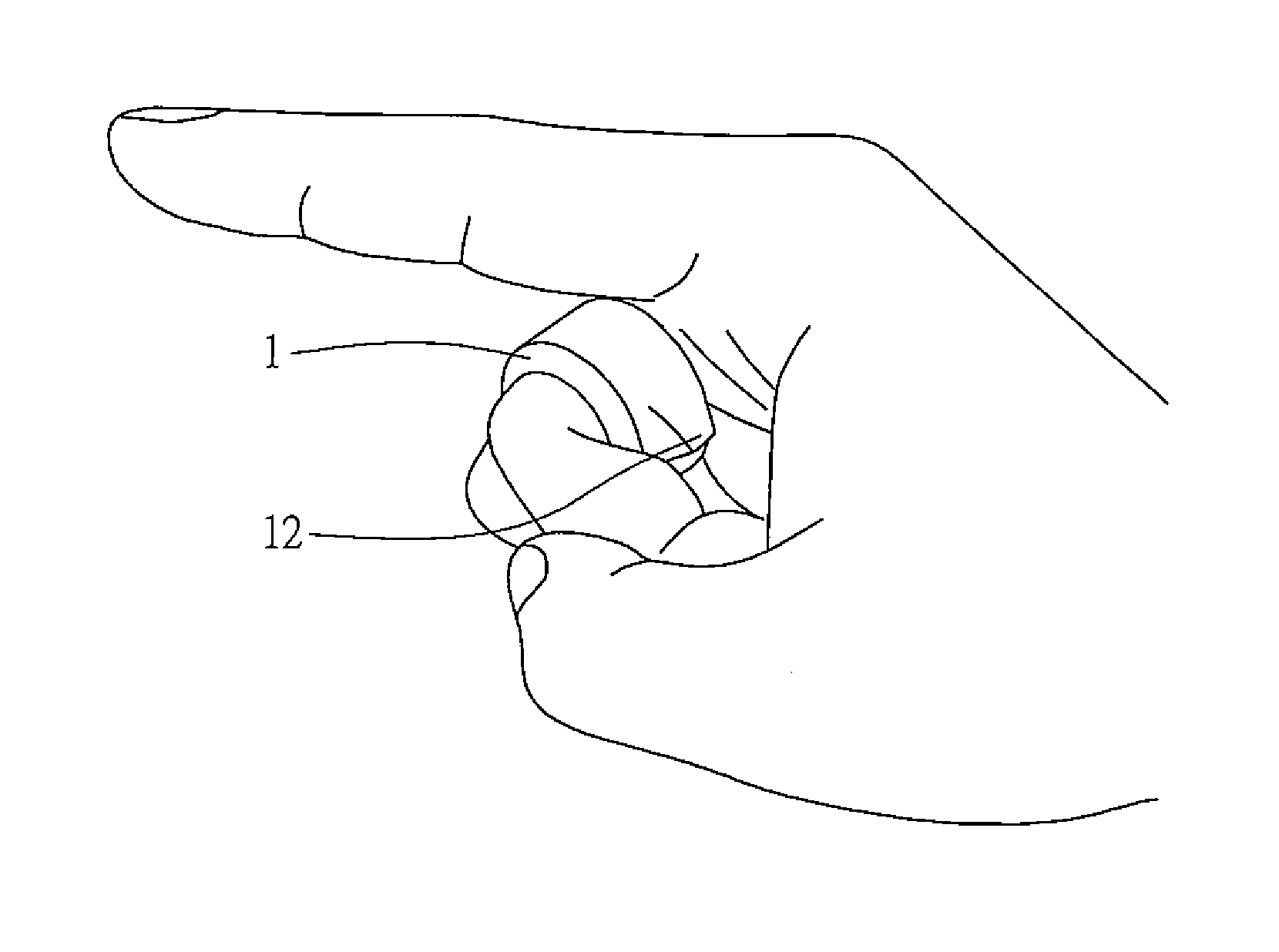
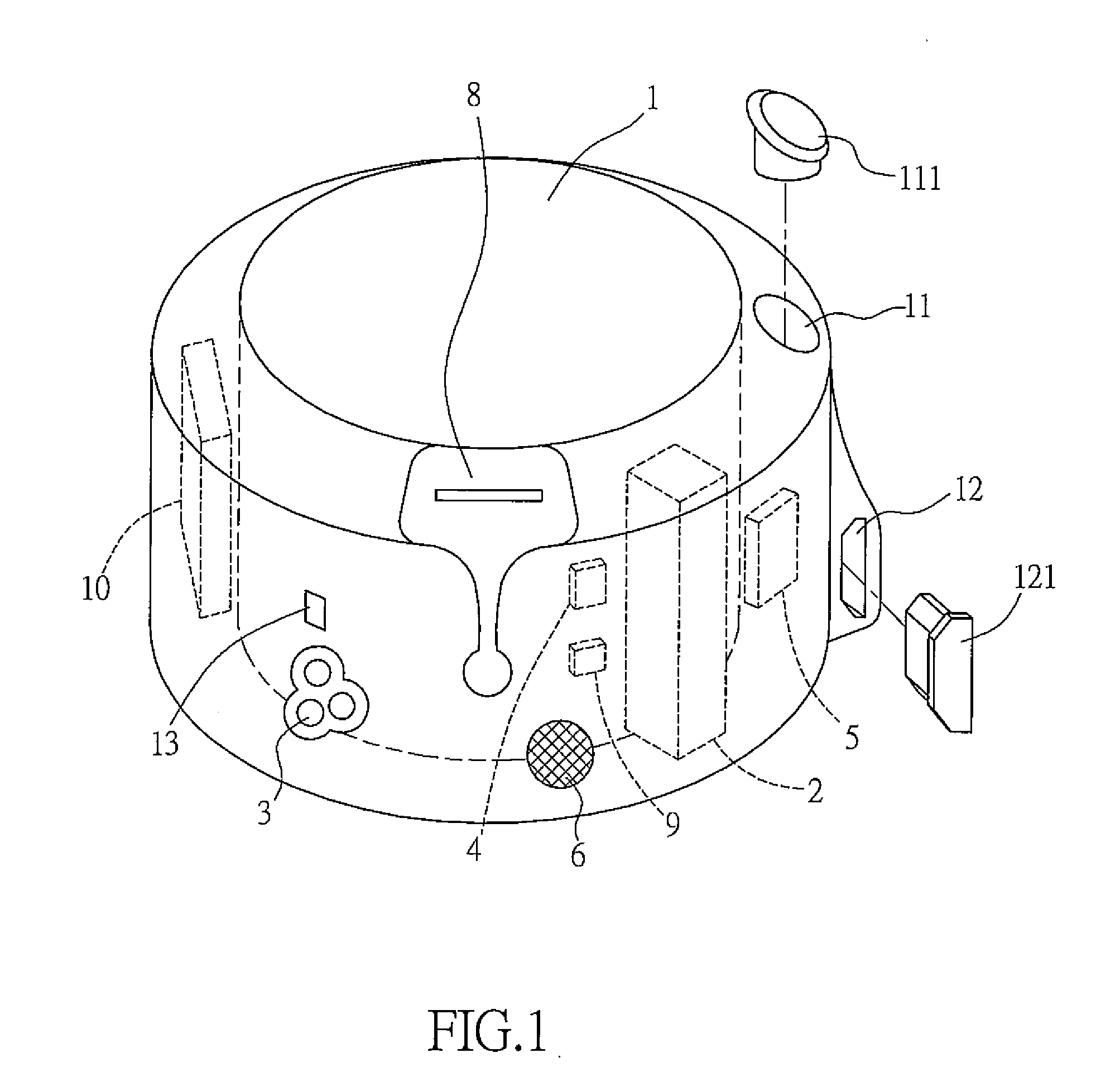
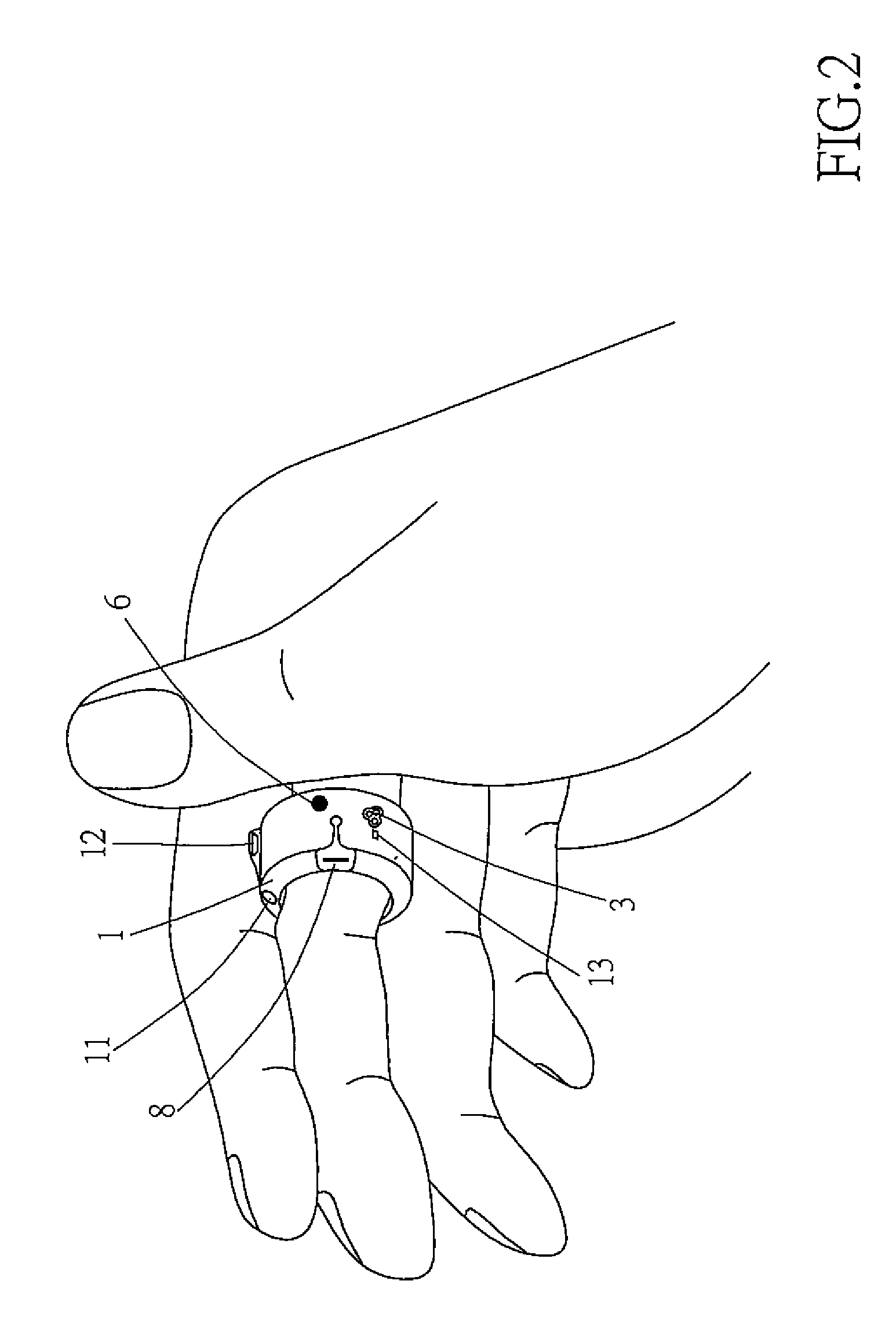
[0025]Refer now to FIG. 1 through FIG. 4, in which FIG. 1 is a schematic perspective view of an embodiment of the 3C smart ring in accordance with the present invention, FIG. 2 demonstrates perspective that the 3C smart ring of FIG. 1 is worn on a user's finger, FIG. 3 shows another state of FIG. 2, and FIG. 4 is a block diagram of the circuitry used in the 3C smart ring in accordance with the present invention. The 3C smart ring of the present invention is capable of coupling or connecting with a ...


PUM


Abstract

A 3C smart ring, capable of coupling 3C products in a cable or wireless communication manner, mainly includes a ring body, a power supply unit, a power switch, a control unit, a transmitting / receiving unit and a microphone. The power supply unit and the transmitting / receiving unit are both coupled electrically with the control unit. The power supply unit is to provide electricity for operating the 3C smart ring. Through the transmitting / receiving unit, the 3C smart ring can couple via wireless signals to 3C networking devices. Further, the power switch and the microphone are located at a lateral side of the ring body, in which the power switch for controlling on / off of the whole ring is coupled electrically with the control unit. The microphone coupled electrically with the control unit is to forward voice signals to the networking 3C devices via the control unit and the transmitting / receiving unit.

Description

[0001]This application claims the benefit of Taiwan Patent Application Serial No. 103112315, filed Apr. 2, 2014, the subject matter of which is incorporated herein by reference.BACKGROUND OF INVENTION [0002]1. Field of the Invention[0003]The invention relates to a 3C smart ring, and more particularly to the 3C smart ring that can be one-handed operated and can communicate via cable or wirelessly with a 3C product such as a smart phone, a tablet, a computer or any built-in operation system the like so as further to forward the user's speech to a speech recognition system of the 3C product for being directly translated into corresponding word sequences, displayed through application software, or integrated with the voice control function of the 3C product to achieve rapid audio input.[0004]2. Description of the Prior Art[0005]With progress in communication technology and the rapid growth and development in the related business segment, multi-function portable electronic products have ...

Claims


Application Information

Patent Timeline
IPC IPC(8): G10L17/22H04R1/02A44C9/00H04R1/08
CPCG10L17/22A44C9/0053H04R1/02H04R1/08H04R1/021H04R2420/07
Inventor TANG, ZHI HONG
Owner WHYNOT TECH
Learn More