F-stop weighted waveform with picture monitor markers

a picture monitor and weighted waveform technology, applied in the field of displaying information on the monitor, can solve the problems of insufficient linear waveform scaling and limited waveform monitors to linear voltage indications

Active Publication Date: 2015-10-08
PROJECT GIANTS LLC
View PDF3 Cites 3 Cited by
  • Summary
  • Abstract
  • Description
  • Claims
  • Application Information

AI Technical Summary

Benefits of technology

The invention describes a method and device that lets people watch the video from a camera in real-time while adjusting the brightness and clarity of the footage. This is done by measuring the brightness of the camera and converting it to a different measure called f-stop. The f-stop measure is then used to adjust the original video by replacing or blending pixels within a certain range. This allows for easier control over the video and improves its overall quality.

Problems solved by technology

A video Waveform Monitor is often also used, but currently these Waveform Monitors are limited to linear voltage indications, with much of the dynamic range near black compressed into just a few mV near 0.
Much like the case for analyzing high dynamic range Radio Frequency (RF) signals, a linear waveform scaling is not adequate.

Method used


Image

  • F-stop weighted waveform with picture monitor markers
  • F-stop weighted waveform with picture monitor markers
  • F-stop weighted waveform with picture monitor markers

Examples


Embodiment Construction

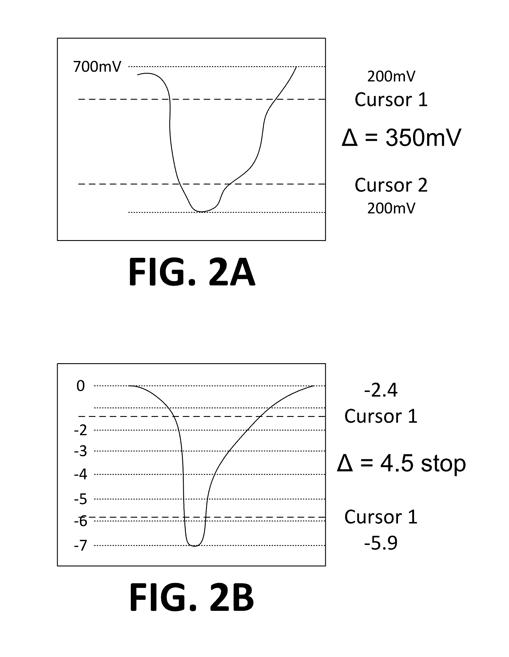
[0017]As mentioned above, embodiments of the invention may be used to assess a live video signal from a cameras in terms of relative f-stops (log2 scale) as well as the traditional, linearly displayed, voltage or IRE level. This effectively converts even an analog camera output into a light-meter for relative lighting and exposure in terms of “stops” or “f-stops”.

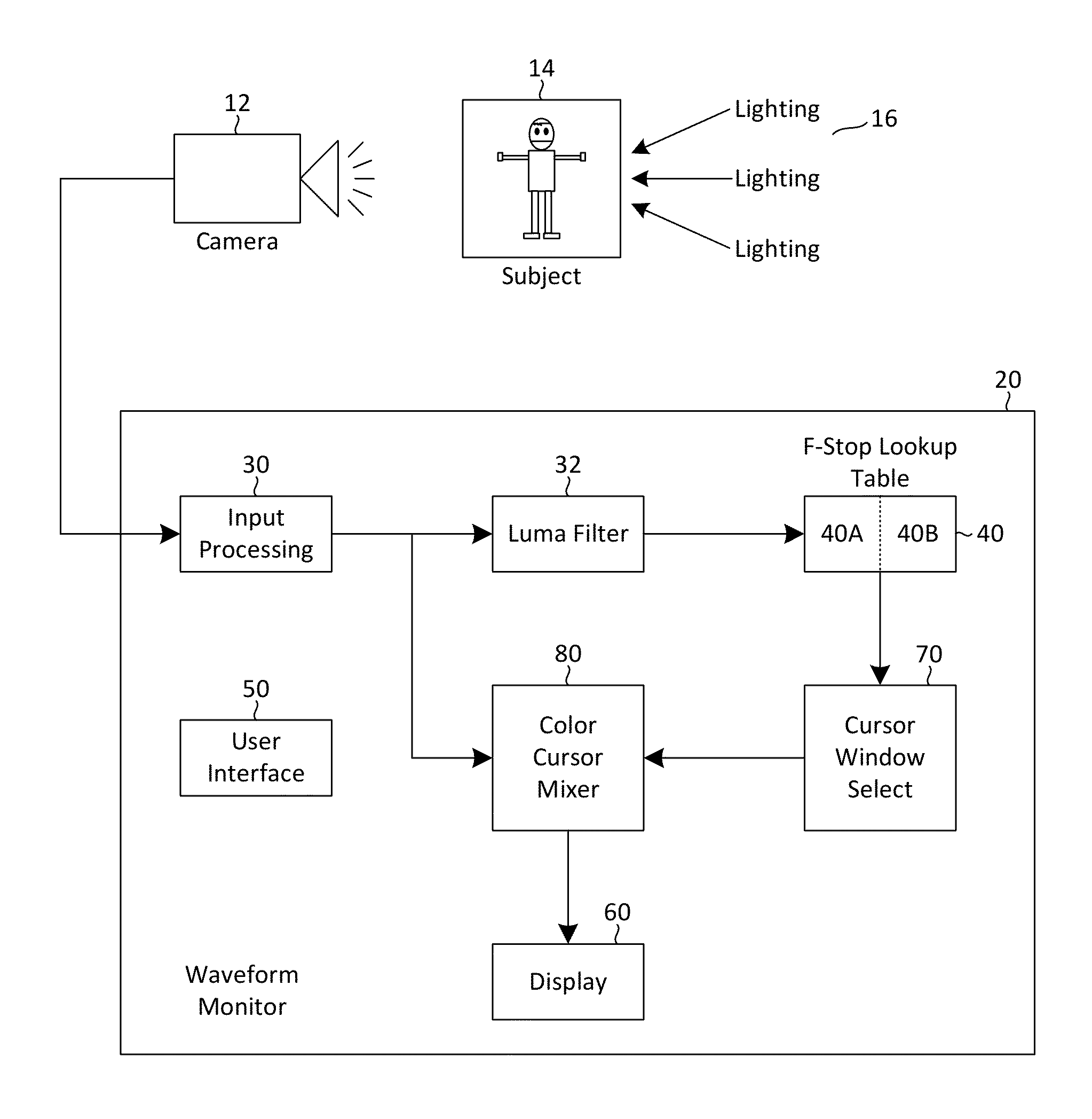
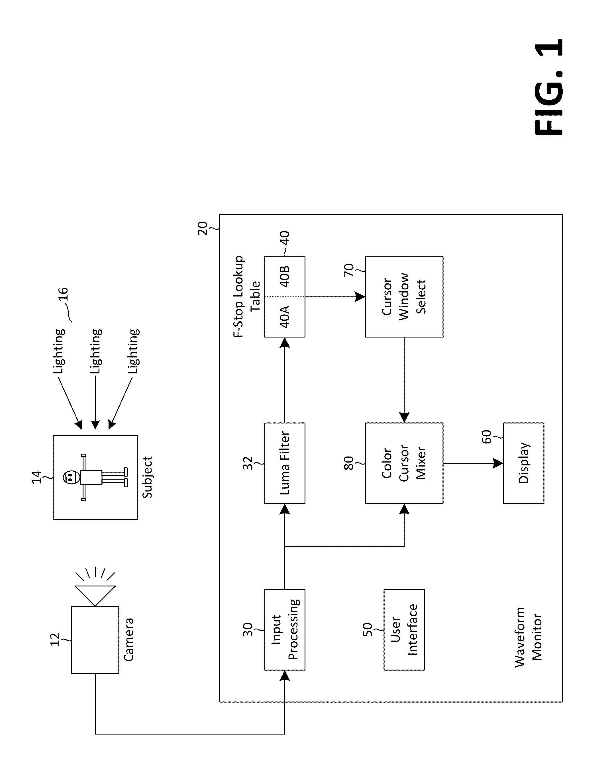
[0018]FIG. 1 is a block diagram showing material portions of an example Video Waveform Monitor according to embodiments of the invention. As illustrated in FIG. 1, a Waveform Monitor 20 is coupled to and receives input from a camera 12 that is pointed at a subject 14 that is lit by lighting 16. The camera 12 typically includes adjustments for aperture and exposure index that may be controlled by a camera operator, or the adjustments may be automatically controlled. The camera output is input to the Waveform Monitor 20.

[0019]The camera 12 output is first processed by an input processor 30 before passing through a filter 32, ...


PUM


Abstract

A waveform monitor for generating a modified image from an original image includes a brightness measuring system to generate brightness values that are then converted to f-stop equivalents. A selector is used to create a range of f-stop values and a modifier changes the original image for selected pixels that fall within the range of f-stop values. The original image may be modified by replacing or blending certain pixels with colorized pixels, i.e., by falsely coloring the original image. Methods of modifying images in this manner are also described.

Description

CROSS REFERENCE TO RELATED APPLICATIONS[0001]This application claims benefit of U.S. Provisional application 61 / 975,566, entitled F-STOP WEIGHTED WAVEFORM DISPLAY WITH PICTURE MARKERS VIA CURSORS, filed on Apr. 4, 2014, the teachings of which are incorporated herein by reference.TECHNICAL FIELD[0002]This disclosure is directed to a method of displaying information on a monitor, and, more particularly, to an apparatus to monitor a camera output signal waveform, and associated methods of use.BACKGROUND[0003]“On-set” or “on-site” video and film production often requires the use of incident and reflected (spot) light-meters to adjust scene lighting and camera gain or aperture. Many times the light-meter measurement and lighting adjustments are done in relative values such as F-stops. F-stops are well known and derive from film exposure and camera aperture or speed adjustment, which is typically adjusted in F-stop increments. The so called F-stop derives from the Focal Ratio or F-number,...

Claims


Application Information

Patent Timeline
IPC IPC(8): G06T7/40
CPCG06T7/408G06T2207/10152G06T2207/10004G06T2207/10024H04N5/2228G06T2207/20208G06T7/80G06T7/90G06T2207/10016H04N23/63H04N23/71G06T5/90G06T2207/10144
Inventor BAKER, DANIEL G.
Owner PROJECT GIANTS LLC
Why Eureka
Try Eureka