Thermographic route examination system and method

Inactive Publication Date: 2015-10-08
GENERAL ELECTRIC CO
View PDF3 Cites 24 Cited by
  • Summary
  • Abstract
  • Description
  • Claims
  • Application Information

AI Technical Summary

Benefits of technology

The patent describes a system and method for inspecting a route, such as a road or track, using a thermographic camera that senses infrared radiation emitted from the route. The camera generates a thermal signature that is compared with healthy thermal signatures of segments of the route that are not damaged. This helps to identify damaged segments of the route, which can be addressed to prevent further damage or mitigate the impact of damage. The system can be used on vehicles or rail vehicles that travel along the route and can also detect differences in temperatures caused by environmental factors such as snow or rain.

Problems solved by technology

Routes that are traveled by vehicles may become damaged over time with extended use.
For example, tracks on which rail vehicles travel may become broken, cracked, pitted, misaligned, or the like, over time.
This damage can pose threats to the safety of the rail vehicles, the passengers located thereon, and nearby persons and property.
For example, the risks of derailment of the rail vehicles can increase when the tracks become damaged.
But, these systems and methods can require additional hardware in the form of a light emitting apparatus, such as a laser light source.
This additional hardware increases the cost and complexity of the systems, and can require specialized rail vehicles that are not used for the conveyance of passengers or cargo.
But, these systems and methods also may require additional hardware to inject the current and to sense the current, and may be prone to false identifications of damage to the route.

Method used


Image

  • Thermographic route examination system and method
  • Thermographic route examination system and method
  • Thermographic route examination system and method

Examples


Embodiment Construction

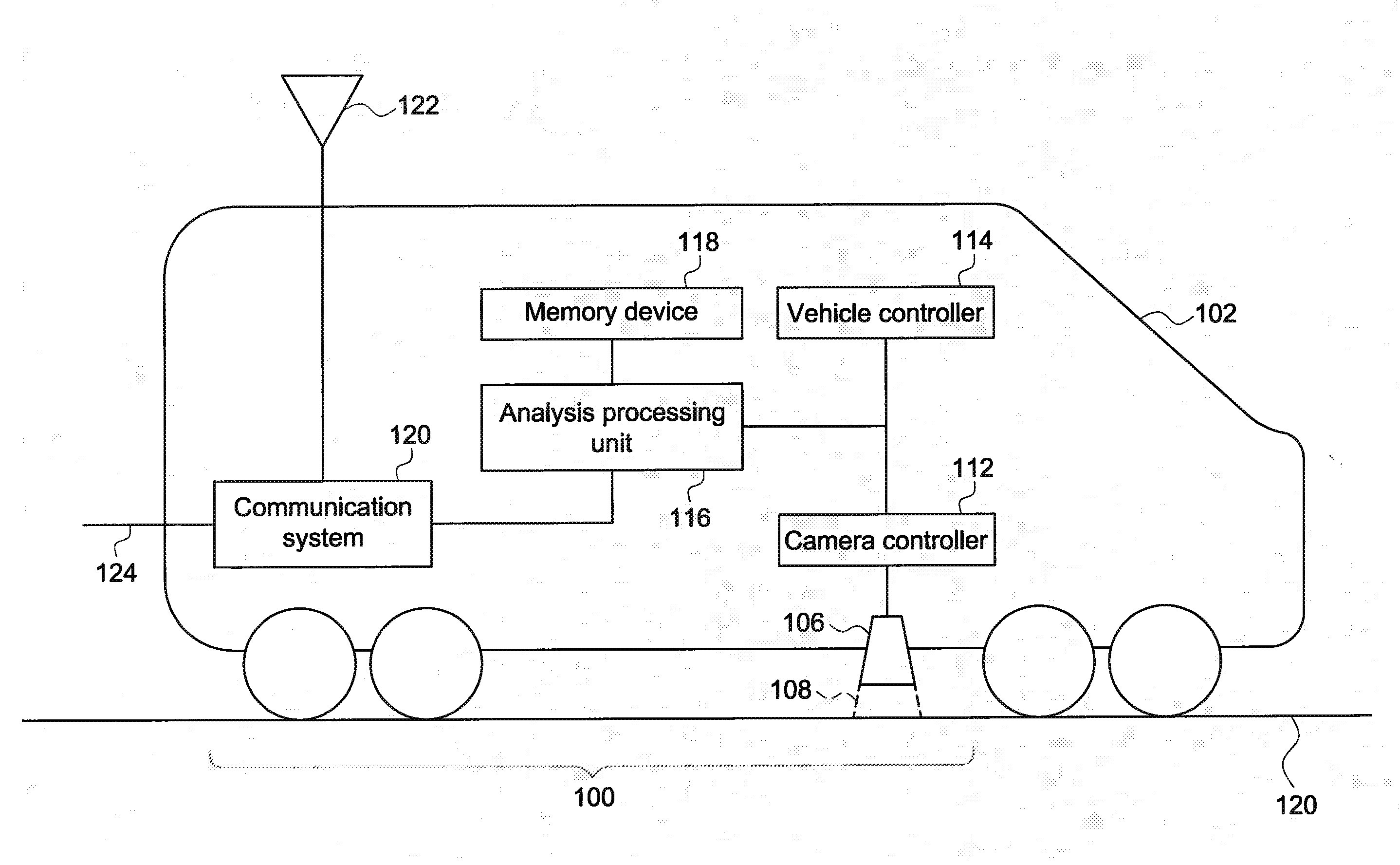
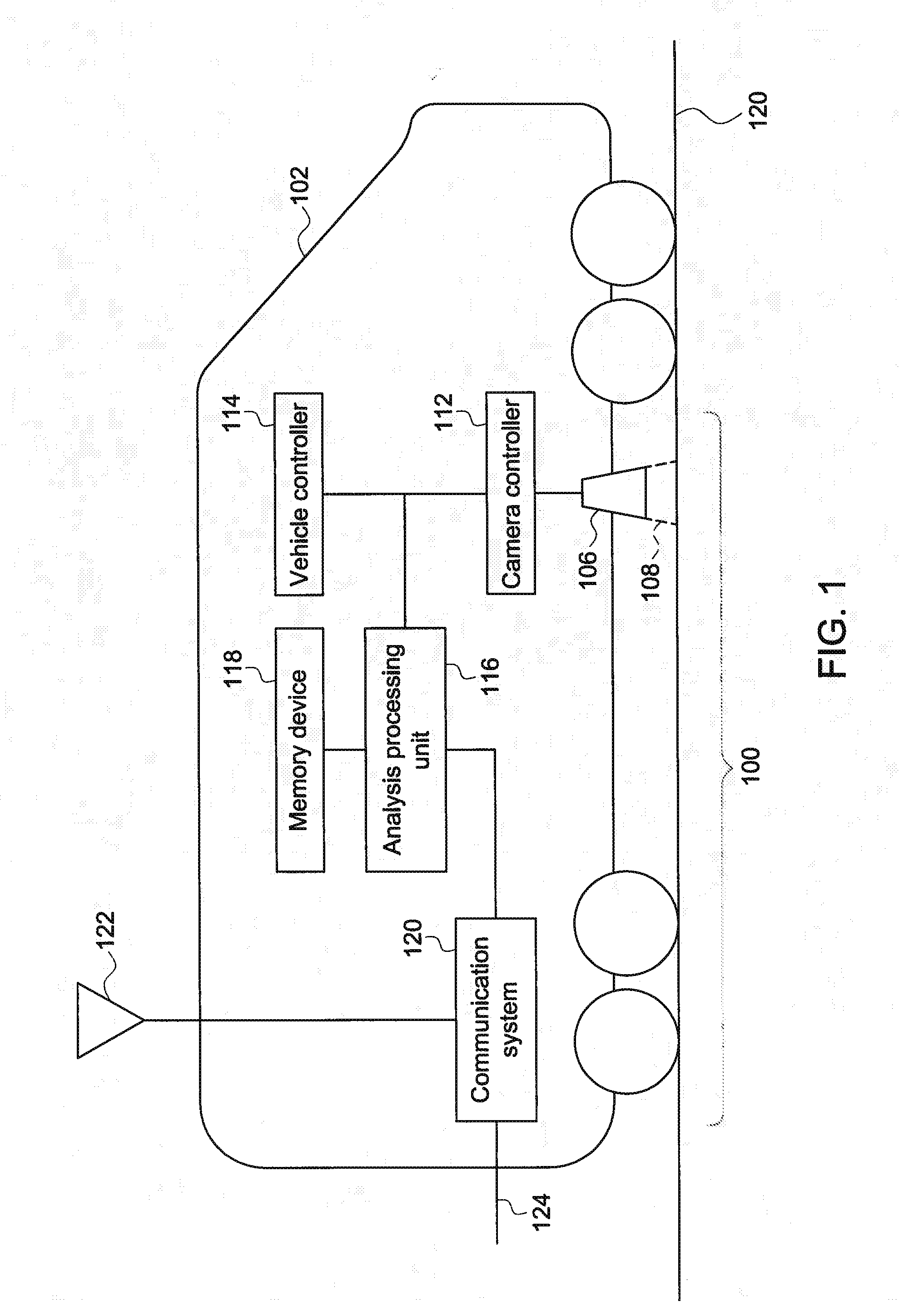
[0015]One or more examples of the inventive subject matter described herein include systems and methods for identifying damaged segments of a route by examining temperatures of the route. Infrared technology can be used to detect thermal signatures in the route, such as in the rails of a track traveled by rail vehicles or other routes traveled by other vehicles. The thermal signatures or patterns to are used to differentiate healthy segments of the route from unhealthy segments. The term “healthy” refers to the extent of damage to the route. For example, a healthy segment of a route can include the portion of the route that has no damage or has a sufficiently reduced amount of damage that vehicles can travel on the route at or near an upper speed limit of the route (e.g., track speed).

[0016]In one aspect, a thermographic or infrared (IR) camera is mounted on a vehicle, and may be oriented toward the route being traveled upon. As the vehicle moves along the route, infrared images are...


PUM


Abstract

A thermographic route examination system includes a thermographic camera, a computer readable memory device, and an analysis processing unit. The thermographic camera is coupled with a vehicle that travels along a route and senses infrared radiation emitted from the route to generate a thermal signature representative of the route. The computer readable memory device stores healthy thermal signatures representative of temperatures of at least one segment of the route that is not damaged. The analysis processing unit receives the thermal signature from the thermographic camera and to determine if the one or more segments of the route are damaged segments of the route based on the thermal signature by comparing the thermal signature of the one or more segments of the route with the one or more healthy thermal signatures to determine if the one or more segments of the route are the damaged segments of the route.

Description

FIELD[0001]Embodiments of the subject matter disclosed herein relate to examining routes traveled by vehicles for damage to the routes.BACKGROUND[0002]Routes that are traveled by vehicles may become damaged over time with extended use. For example, tracks on which rail vehicles travel may become broken, cracked, pitted, misaligned, or the like, over time. This damage can pose threats to the safety of the rail vehicles, the passengers located thereon, and nearby persons and property. For example, the risks of derailment of the rail vehicles can increase when the tracks become damaged.[0003]Some known systems and methods that inspect the tracks involve emitting visible markers on the tracks and optically monitoring these markers to determine if the tracks have become misaligned. These visible markers may be created using laser light, for example. But, these systems and methods can require additional hardware in the form of a light emitting apparatus, such as a laser light source. This...

Claims


Application Information

Patent Timeline
IPC IPC(8): G01J5/52G01J5/04
CPCG01J5/52G01J2005/0085G01J5/041B61K9/10G01N21/88G01J2005/0077G01N25/72
Inventor NAITHANI, NIDHIRAO, DATTARAJ JAGDISHBIND, ANJUCHAKI, SREYASHI DEY
Owner GENERAL ELECTRIC CO
Why Eureka
Try Eureka