Air Mass Flowmeter

a technology of air mass flow and flowmeter, which is applied in the direction of volume/mass flow measurement, measurement devices, instruments, etc., can solve the problems of signal drift in the sensor element, inability to accurately measure the air mass flow, and influence the measurement results of the sensor elements in a particularly disadvantageous way, so as to eliminate the corruption of the measurement results

Active Publication Date: 2015-10-08
VITESCO TECH GERMANY GMBH
View PDF0 Cites 2 Cited by
  • Summary
  • Abstract
  • Description
  • Claims
  • Application Information

AI Technical Summary

Benefits of technology

[0011]It is an object of the invention to eliminate the corruption of the measurement results due to contamination of the sensor element or at least to keep it within tight limits.

Problems solved by technology

During the development of modern air mass flowmeters that operate on the basis of sensor elements in the form of microelectromechanical systems (MEMS), it has become apparent that the measurement results of the sensor elements are influenced in a particularly disadvantageous way by contamination.
Contamination can be caused by, for example, oil droplets in the air mass flow, and results in signal drift in the sensor element over time.
The signal drift may lead to incorrect measurement values for the air mass flow.

Method used


Image

  • Air Mass Flowmeter
  • Air Mass Flowmeter
  • Air Mass Flowmeter

Examples


Embodiment Construction

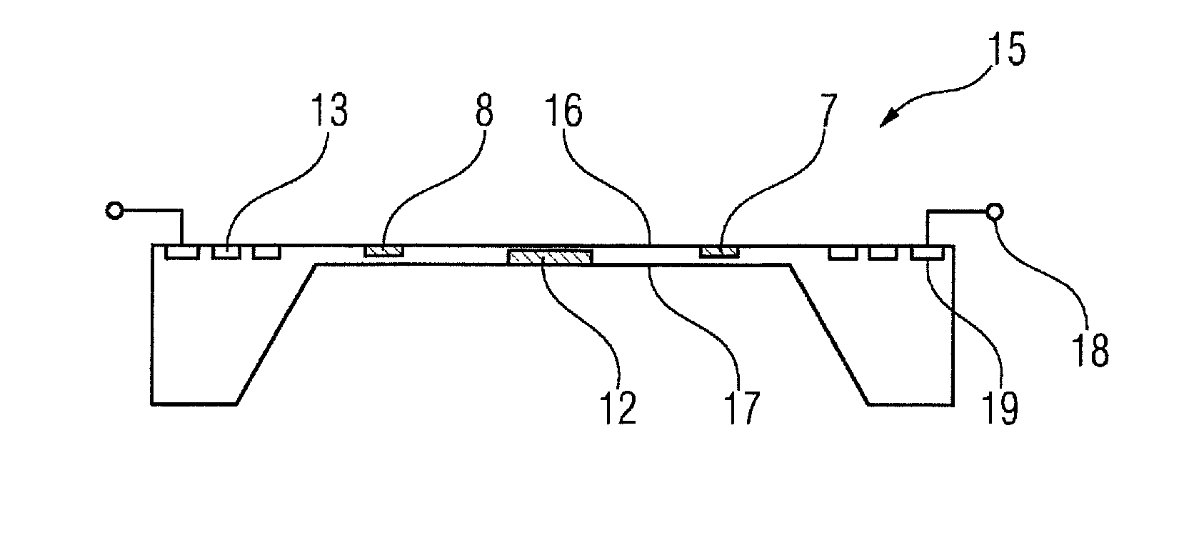
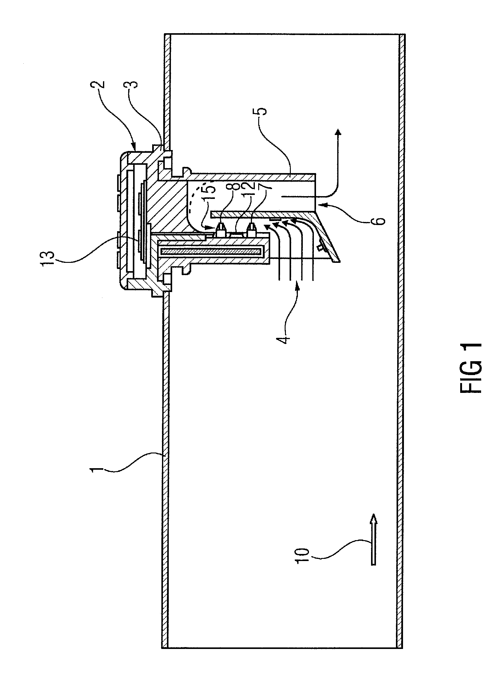
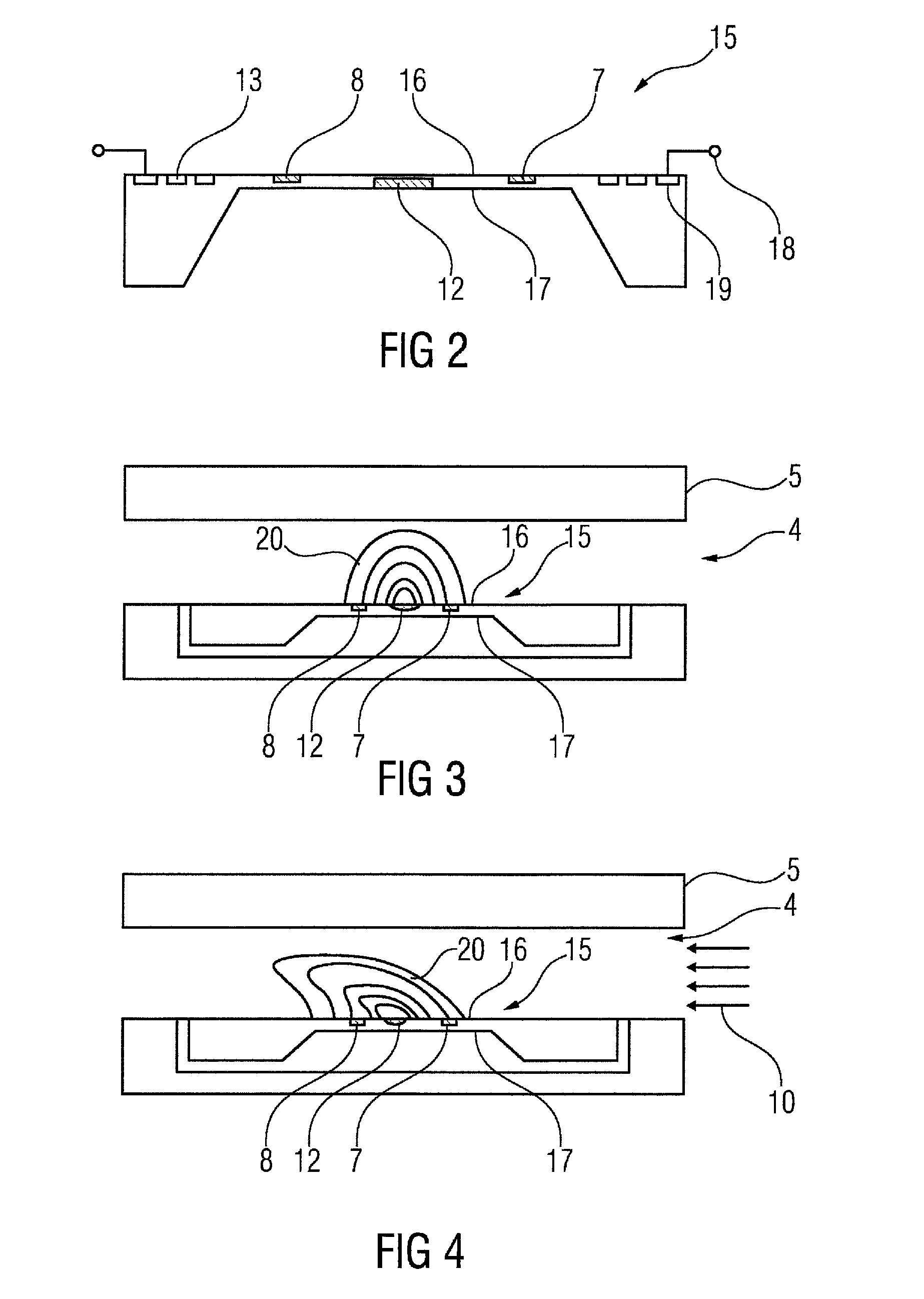
[0023]FIG. 1 shows a mass flow sensor in the form of an air mass flowmeter 2. In this example, the air mass flowmeter 2 is shown as an insertion finger inserted into an intake pipe 1 and is fixedly connected to the intake pipe 1. The intake pipe 1 leads a mass flow, which is an air mass flow 10, to the cylinders of an internal combustion engine. To efficiently burn the fuel in the cylinders of an internal combustion engine, it is necessary to obtain accurate information about the available air mass. Based on the air mass available, it is possible to infer the amount of the available oxygen necessary for burning the fuel injected into the cylinder. Furthermore, the air mass flowmeter 2 in FIG. 1 has a first temperature sensor element 7 and a second temperature sensor element 8. The first temperature sensor element 7 and the second temperature sensor element 8 are arranged at different locations. The temperature sensor elements 7, 8 are generally formed from resistors or thermopiles t...


PUM


Abstract

An air mass flowmeter having a sensor element of microelectromechanical design, a heating element, and a temperature sensor element. The temperature sensor element is a thermocouple assembly having a multiplicity of thermocouples connected in series. Each thermocouple is a first metal conductor and a second, different metal conductor connected to one another at one end by a connection point. To reduce the distortion of measurement results by the soiling of the sensor element, the first thermocouple(s) and the last thermocouple(s) of the thermocouple assembly are polarized such that an electrical current flows first through the second metal conductor and then through the first metal conductor in each case. The remaining thermocouples of the thermocouple assembly are polarized such that the electrical current flows first through the first metal conductor and then through the second metal conductor.

Description

CROSS REFERENCE TO RELATED APPLICATIONS[0001]This is a U.S. national stage of application No. PCT / EP2013 / 072852, filed on Nov. 1, 2013. Priority is claimed on German Application No.: DE102012220019.3 filed Nov. 2, 2012, the content of which is incorporated herein by reference.BACKGROUND OF THE INVENTION[0002]1. Field of the Invention[0003]The invention relates to an air mass flowmeter having a microelectromechanical sensor element, a heating element, and at least one temperature sensor element. The temperature sensor element is a thermal element. The thermal element comprises a large number of thermocouples connected in series and through which an electric current flows in succession. A thermocouple comprises a first metal conductor and a second metal conductor connected to one another in each case at an end by a connecting point, the first metal conductor and the second metal conductor are formed from different metals.[0004]2. Detailed Description of the Prior Art[0005]Air mass flo...

Claims


Application Information

Patent Timeline
Patent Type & Authority Applications(United States)
IPC IPC(8): G01F1/688G01F1/684
CPCG01F1/6845G01F1/6888
Inventor KNITTEL, THORSTENSETESCAK, STEPHEN
Owner VITESCO TECH GERMANY GMBH
Why Eureka
Try Eureka