
Shimming method for correcting inhomogeinity of a static magnetic field generated by a magnet of a nuclear magnetic resonance machine

Active Publication Date: 2015-10-01
ESAOTE
View PDF4 Cites 3 Cited by
  • Summary
  • Abstract
  • Description
  • Claims
  • Application Information

AI Technical Summary

Benefits of technology

The present invention provides a method for correcting magnetic field in a magnetic resonance imaging machine using a superquadric surface. The method is based on the construction of a solution to Laplace's equation using a spherical coordinate transformation and a field expansion. The use of a superquadric surface allows for better correction of the magnetic field and simplifies the problem. The method can be used in a spherical coordinate system and is applicable to both symmetrical and non-symmetrical problems. The use of a superquadric surface as a boundary surface delimiting the FOV results in a more efficient and effective solution.

Problems solved by technology

At the beginning, the magnetic field generated by the magnet is strongly affected by inhomogeneity caused by manufacturing tolerances and environmental interferences, which have highly detrimental effects on image quality.
While this condition may be acceptable in certain cases, when allowed by the anatomy of the patient under examination, in other cases it leads to unacceptable artifacts, such as in sagittal T2-weighted Fast Spin Echo (FSE).
The attempt to contain the entire image volume with one of the quadrics inevitably leads to a considerable increase of the geometric dimensions of the apparatus.
This will necessarily increase the size, weight, amount of magnetic material, etc., thereby leading to a rapid increase of the costs of manufacture, installation, maintenance and operation of the magnetic resonance imaging machine.
Therefore, there currently exists a geometric problem preventing shimming volume-FOV overlap, which is yet unsolved by prior art shimming methods.

Method used


Image

  • Shimming method for correcting inhomogeinity of a static magnetic field generated by a magnet of a nuclear magnetic resonance machine
  • Shimming method for correcting inhomogeinity of a static magnetic field generated by a magnet of a nuclear magnetic resonance machine
  • Shimming method for correcting inhomogeinity of a static magnetic field generated by a magnet of a nuclear magnetic resonance machine

Examples


Embodiment Construction

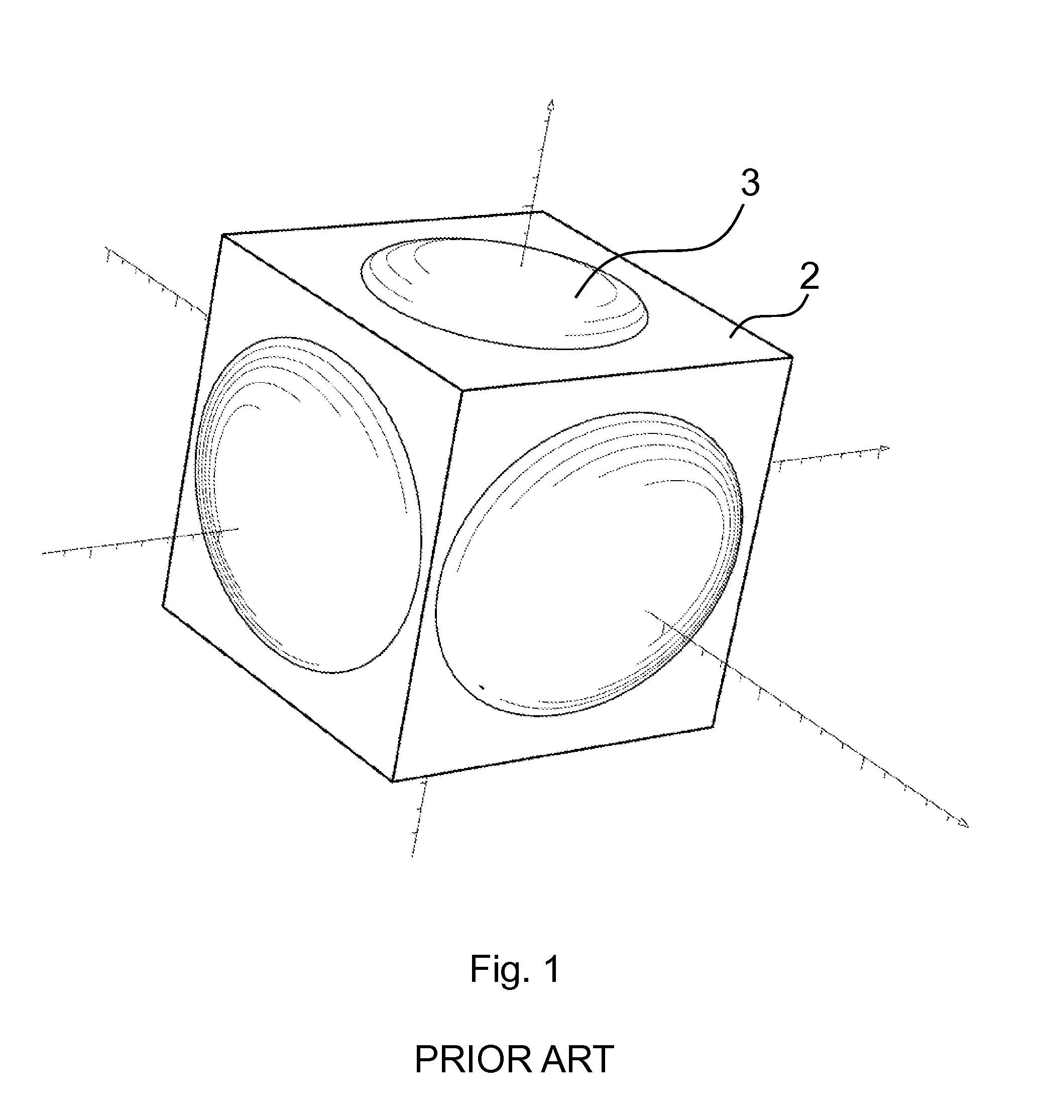
[0081]FIG. 1 shows the shimming volume with a quadric surface 3 and the FOV 2 or image volume according to a prior art shimming method, particularly in a 0.31 T magnet.

[0082]The quadric surface 3 is an oblate spheroid with semiaxes of 82×95 mm along the axis Y and the axes X and Z respectively, whereas the FOV 2 is a cube with a side length of 140 mm.

[0083]In this configuration, some areas of the FOV 2 are apparently external to the shimming volume, namely near the vertices of the cube, and some areas concerned by the shimming process do not fall within the FOV 2, namely the central portions of the cube faces.

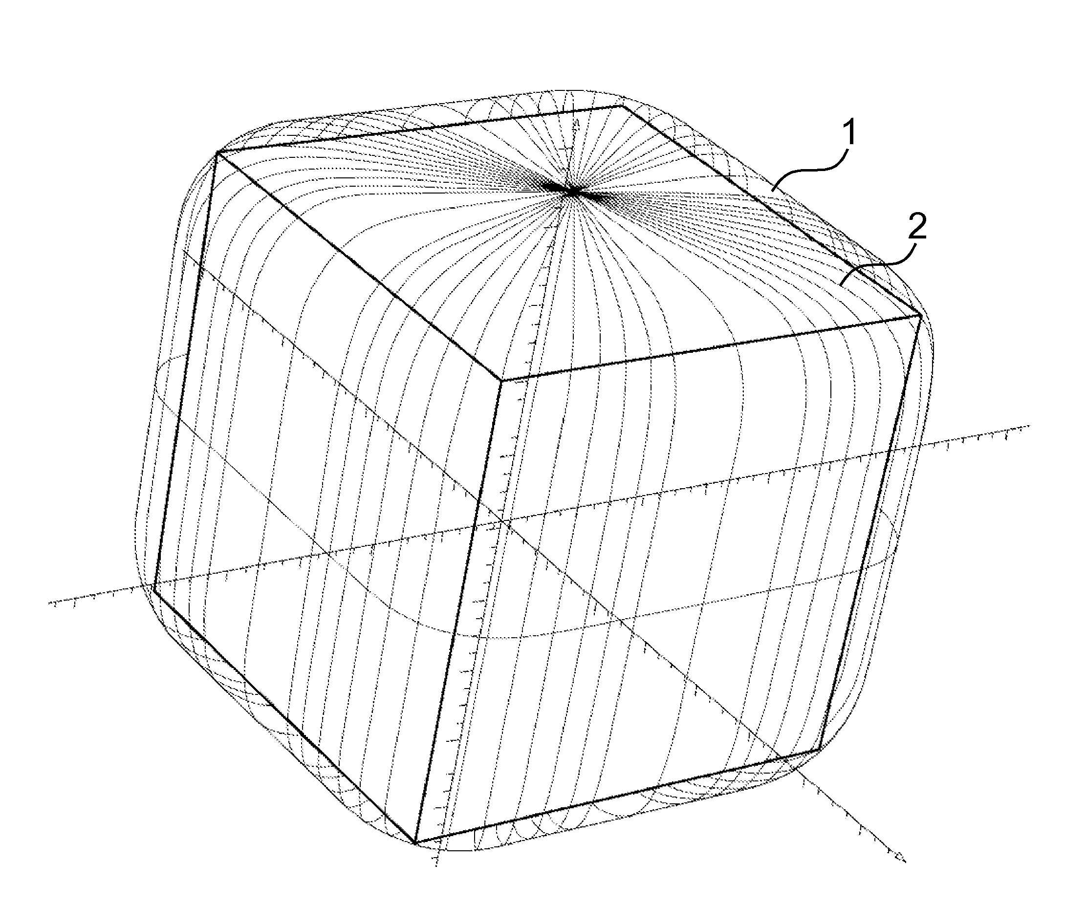
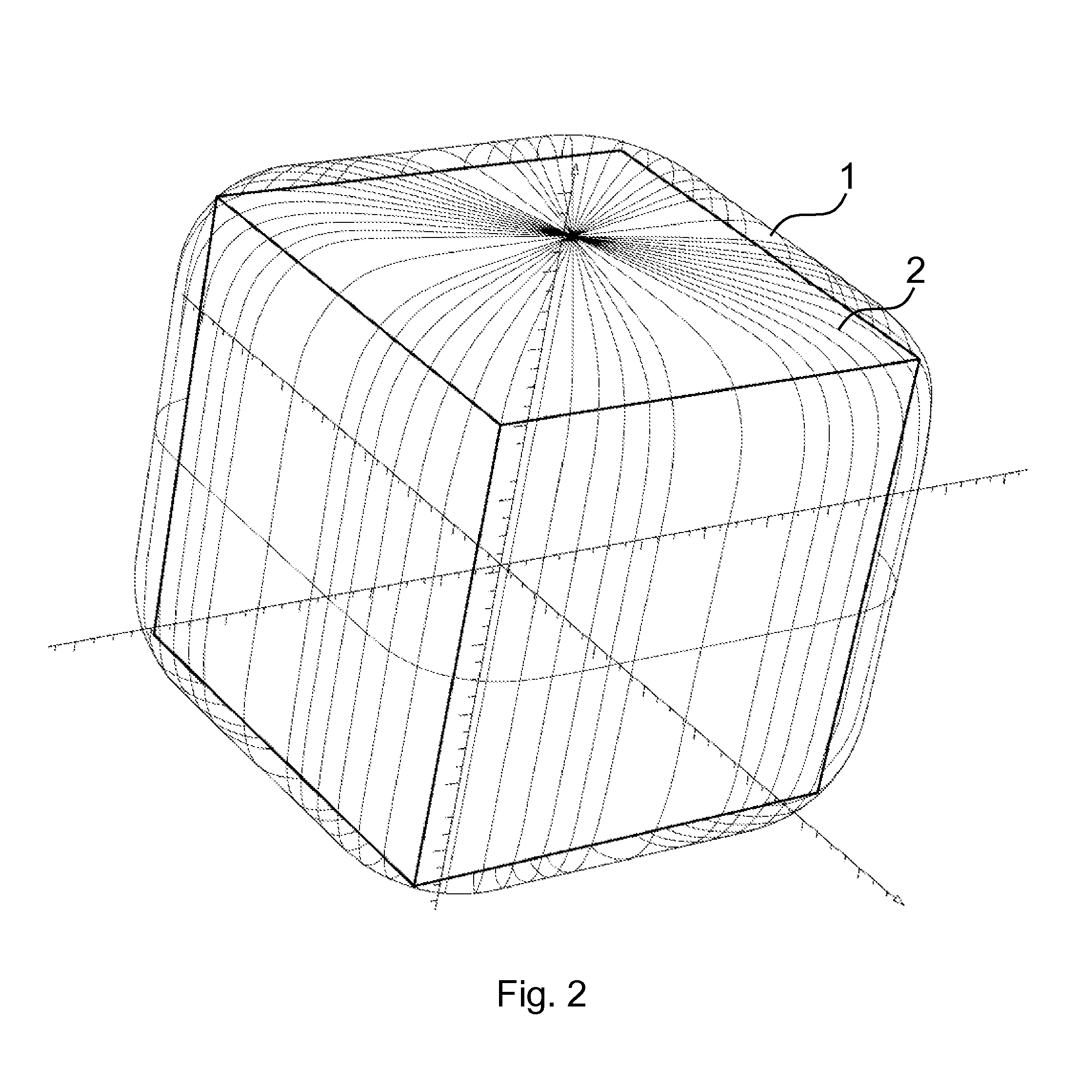
[0084]FIG. 2 shows the FOV 2 and the superquadric shimming surface 1 of the present method, and particularly a superquadric 1 whose surface contains the entire FOV 2.

[0085]Considering the general Equation (1) the following values have been set for the parameters (α, β, γ, ν, a, b, c, p, q):

α=6, β=6, γ=6, ν=6,

a=85, b=82, c=85, p=2, q=2

[0086]The Equation obtained thereby is as fo...


PUM


Abstract

A shimming method for correcting inhomogeneity of a static magnetic field generated by a magnet of a nuclear magnetic resonance imaging machine includes: measuring the magnetic field at a plurality of points over a reference surface; generating a polynomial that solves Laplace's equation with boundary conditions given on the reference surface, the polynomial representing the magnetic field on the reference surface and having a plurality of harmonic terms, each associated with a coefficient; determining the coefficients from the field sampling values; defining a grid for positioning a plurality of correction elements and relating it to the field structure; and calculating the position and magnitude parameters of the correction elements, such that the correction elements affect the coefficients of the magnetic field to obtain the desired field characteristics, wherein the reference surface is a superquadric surface, such that the magnetic field is corrected in a volume delimited by the superquadric surface.

Description

FIELD OF THE INVENTION[0001]The present invention relates to a shimming method for correcting inhomogeneity of a static magnetic field generated by a magnet of a nuclear magnetic resonance imaging machine, which includes the steps of: measuring the magnetic field at a plurality of points, over a reference surface; generating a polynomial that solves Laplace's equation with boundary conditions given on the reference surface, said polynomial representing the magnetic field on the reference surface and comprising a plurality of harmonic terms, each associated with a coefficient; determining the coefficients from the field sampling values; defining a grid for positioning a plurality of correction elements and relating it to the field structure; and calculating the position and magnitude parameters of said correction elements, such that the correction elements affect the coefficients of the magnetic field to obtain the desired field characteristics.BACKGROUND OF THE INVENTION[0002]Shimmi...

Claims


Application Information

Patent Timeline
IPC IPC(8): G01R33/565G01R33/383G01R33/3873G01R33/48
CPCG01R33/56572G01R33/3873G01R33/383G01R33/4822
Inventor PUNZO, VINCENZO
Owner ESAOTE
Learn More