
Endoscopic shank instrument

a shank instrument and endoscope technology, applied in the field of endoscope shank instruments, can solve the problems of disadvantageous cross-sectional size of instruments, comparatively complex mechanical construction of instruments in the region of tool carriers, and inability to meet the needs of patients, etc., and achieve the effect of simple and compact construction

Active Publication Date: 2015-09-24
RICHARD WOLF GMBH
View PDF2 Cites 6 Cited by
  • Summary
  • Abstract
  • Description
  • Claims
  • Application Information

AI Technical Summary

Benefits of technology

The invention is about an improved design for an endoscopic shank instrument that can be used for coagulation purposes. The device has a flexible circuit board that allows for a more slender design and better adaptability to tight space conditions. The instrument also has two jaw parts that can be controlled by a pivot joint. The jaw parts are connected to the circuit board through a mounting body that is rotatable on the pivot joint. This design allows for a more effective and reliable control of the jaw parts, even when using pull cables.

Problems solved by technology

Different joint mechanisms are used in this context, but these however all lead to a comparatively complex mechanical construction of the instrument in the region of the tool carrier.
This complexity is additionally increased due to the fact that guides for the electrical cable connections, via which electrodes arranged on the tool are conductively connectable to a voltage source arranged proximally of the shank, must be provided within the tool carrier.
This all has a disadvantageous effect on the cross-sectional size of the instrument, which actually should be kept as small as possible.

Method used


Image

  • Endoscopic shank instrument
  • Endoscopic shank instrument
  • Endoscopic shank instrument

Examples


Embodiment Construction

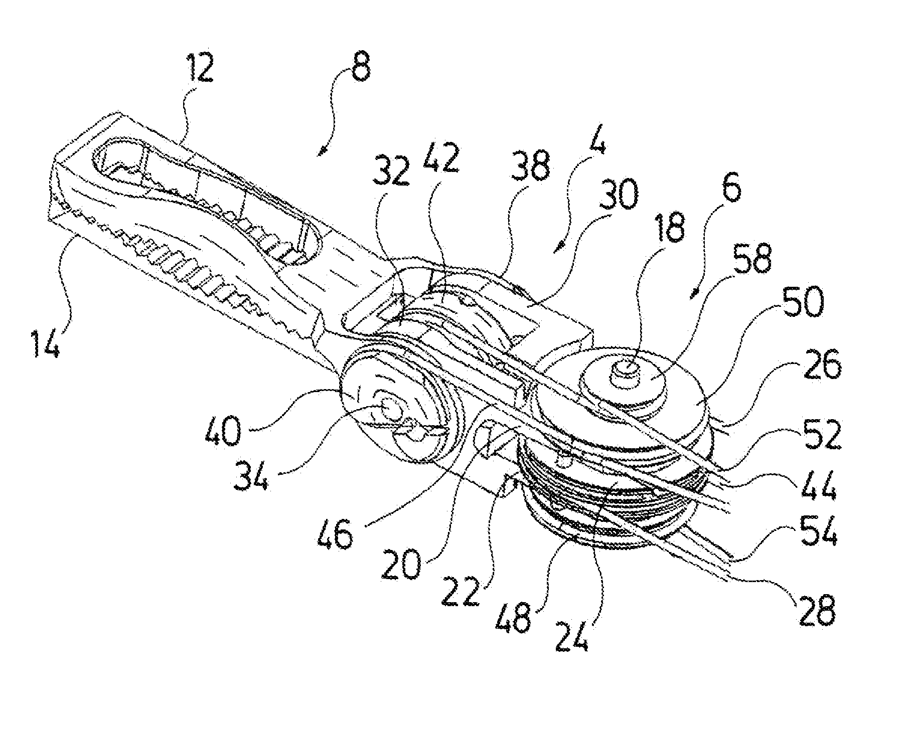
[0036]With regard to the endoscopic shank instrument represented in FIG. 1, it is the case of a coagulation forceps. The coagulation forceps comprises a shank 2 which is designed as a hollow shank and distally of which a tool carrier 4 is arranged. The tool carrier 4 is formed from polyetheretherketone and it is thus not electrically conductive. The tool carrier 4 is bendable relative to the shank 2 via a joint connection 6. At its distal end, the tool carrier 4 carries a jaw tool 8 with two jaw parts 12 and 14 which are pivotable relative to one another about a joint pivot 10. As is explained in more detail hereinafter, the control of the two jaw parts 12 and 14 as well as of the tool carrier 4 is effected via pull cables which are led through the shank 2 to proximally of the shank 2, where they are actively connected to a control device 16. With regard to the control device 16 it can be the case of a handle, as is described e.g. in DE 10 2011 085 512 A1, if the instrument is an in...


PUM


Abstract

An endoscopic shank instrument has a tool carrier which is arranged at a distal shank end, is bendable relative to the shank and carries a tool. The tool includes at least one electrode which is conductively connectable to a voltage source via an electrical lead led through the shank. The lead is formed by a flexible circuit board in the region of the tool carrier and of the bending of the tool carrier.

Description

CROSS REFERENCE TO RELATED APPLICATIONS[0001]This application claims the benefit of priority under 35 U.S.C. §119 of German Patent Application 10 2014 205 006.5 filed Mar. 18, 2014, the entire contents of which are incorporated herein by reference.FIELD OF THE INVENTION[0002]The invention relates to an endoscopic shank instrument with a tool carrier which is arranged at the distal shank end, is bendable relative to the shank and carries a tool having at least one electrode, the electrode being conductively connectable to a voltage source via an electrical lead led through the shank.BACKGROUND OF THE INVENTION[0003]A multitude of medical treatment methods with which electrical energy is applied in a targeted manner onto body tissue to be treated, has been applied for some time now. Examples of this are coagulation, electrotomy and the ablation of body tissue. These methods are also applied in the field of minimal-evasive surgery. The endoscopic instruments which are applied there usu...

Claims


Application Information

Patent Timeline
IPC IPC(8): A61B18/14
CPCA61B18/1492A61B2018/00589A61B2018/00184A61B18/1445
Inventor MUNNIG, SORENWEHRHEIM, FRANKPRESTEL, STEPHANEIDNER, PHILIPP
Owner RICHARD WOLF GMBH
Learn More