
Hybrid high voltage direct current converter system and method of operating the same

a converter system and high-voltage direct current technology, applied in power conversion systems, electric power transfer ac networks, circuit arrangements, etc., can solve problems such as increasing the probability of system instability, capacitor banks, ac and dc harmonic filters are capital-intensive, and the probability of control overshoots and undershoots is increasing

Inactive Publication Date: 2015-09-10
GENERAL ELECTRIC CO
View PDF3 Cites 28 Cited by
  • Summary
  • Abstract
  • Description
  • Claims
  • Application Information

AI Technical Summary

Benefits of technology

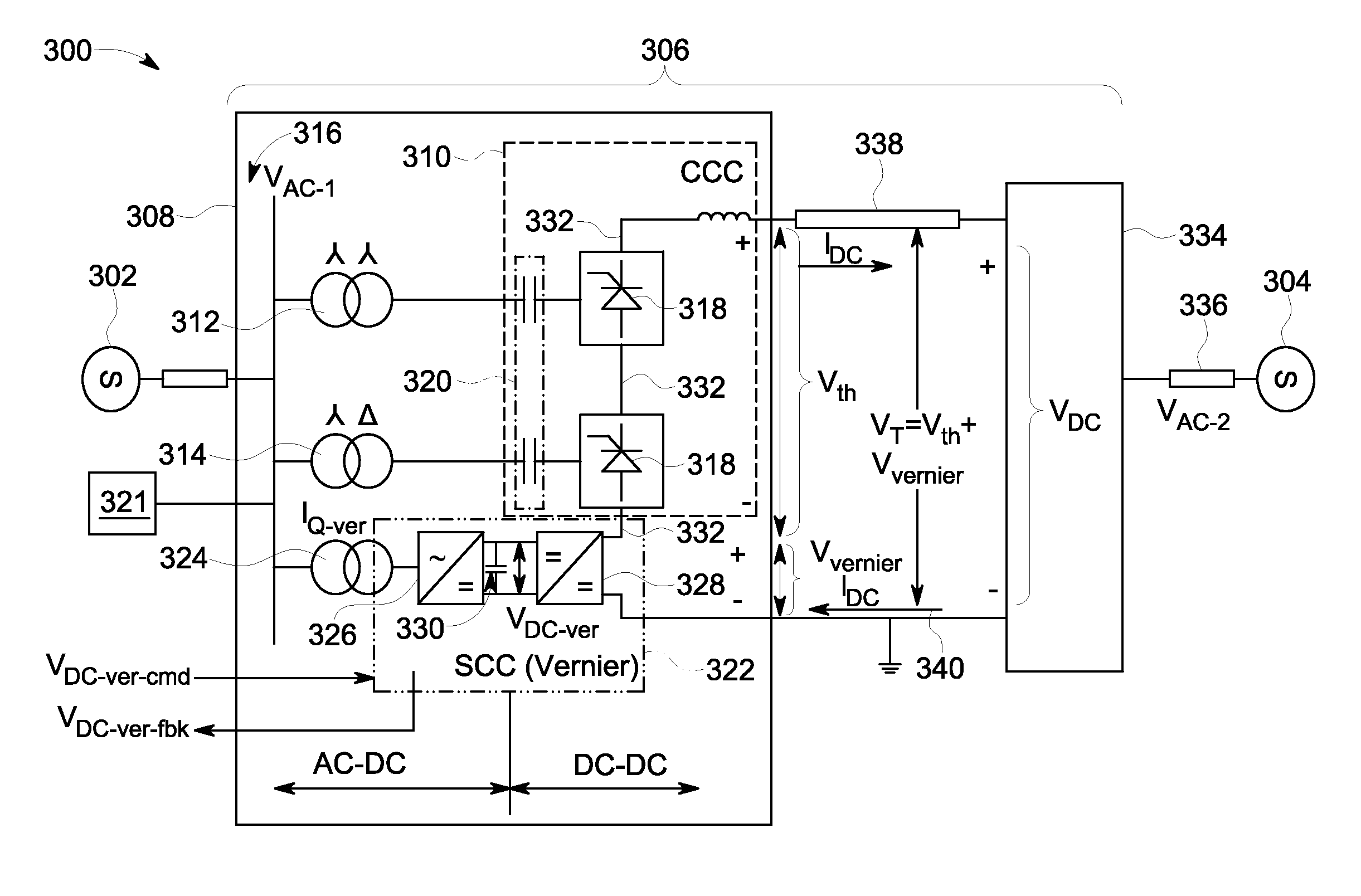
This patent describes a method for controlling a hybrid high voltage direct current (HVDC) converter system. The system includes a DC bus and two types of converters, that is, a capacitor commutated converter (CCC) and a self-commutated converter (SCC). These converters are coupled in series with the DC bus. The CCC induces a first voltage on the DC bus and the SCC induces a second voltage on the DC bus. These two voltages are combined to create a total DC voltage on the DC bus. The method allows for regulation of the total DC voltage by either the CCC or the SCC, or a combination of both. The regulation can be done simultaneously or separately. The technical effect of this patent is to provide a precise and flexible method for controlling the voltage and current in a hybrid HVDC converter system. This can help to improve the stability and performance of the system.

Problems solved by technology

Since the values of the commands are variable, the control scheme for the second converter station my shift modes between the CC loop and the VC loop on a frequent basis, thereby increasing a probability of system instability.
Also, the use of VDCOLs may increase the frequency of the control loops hitting a limit without any further bandwidth to facilitate control, thereby increasing the probability of control overshoots and undershoots.
Such capacitor banks, associated switchgear, and AC and DC harmonic filters are capital-intensive due to the land required and the amount of large equipment installed.
In addition, a significant investment in replacement parts and preventative and corrective maintenance activities increases operational costs.
Therefore, increased reactive power flow, commutation failure, and lower margins to recovery from DC system disturbances may become more probable.

Method used


Image

  • Hybrid high voltage direct current converter system and method of operating the same
  • Hybrid high voltage direct current converter system and method of operating the same
  • Hybrid high voltage direct current converter system and method of operating the same

Examples


Embodiment Construction

[0022]In the following specification and the claims, reference will be made to a number of terms, which shall be defined to have the following meanings.

[0023]The singular forms “a”, “an”, and “the” include plural references unless the context clearly dictates otherwise.

[0024]“Optional” or “optionally” means that the subsequently described event or circumstance may or may not occur, and that the description includes instances where the event occurs and instances where it does not.

[0025]Approximating language, as used herein throughout the specification and claims, may be applied to modify any quantitative representation that could permissibly vary without resulting in a change in the basic function to which it is related. Accordingly, a value modified by a term or terms, such as “about” and “substantially”, are not to be limited to the precise value specified. In at least some instances, the approximating language may correspond to the precision of an instrument for measuring the val...


PUM


Abstract

A hybrid HVDC converter system includes a DC bus, at least one capacitor commutated converter (CCC) and at least one self-commutated converter (SCC) coupled in series through the DC bus. The CCC induces a first voltage on the DC buses, the SCC induces a second voltage on the DC bus, the first voltage and the second voltage are summed to define a total DC voltage. The method includes at least one of regulating the total DC voltage induced on the DC buses including regulating the first DC voltage through the CCC and regulating the second DC voltage through the SCC substantially simultaneously, regulating the total DC voltage induced on the DC bus including regulating the second DC voltage through the SCC, and regulating the total DC voltage induced on the DC bus including regulating the first DC voltage through the CCC.

Description

BACKGROUND[0001]The field of the invention relates generally to high voltage direct current (HVDC) transmission systems and, more particularly, to hybrid HVDC converter systems and a method of operation thereof.[0002]At least some of known electric power generation facilities are physically positioned in a remote geographical region or in an area where physical access is difficult. One example includes power generation facilities geographically located in rugged and / or remote terrain, for example, mountainous hillsides, extended distances from the customers, and off-shore, e.g., off-shore wind turbine installations. More specifically, these wind turbines may be physically nested together in a common geographical region to form a wind turbine farm and are electrically coupled to a common alternating current (AC) collector system. Many of these known wind turbine farms include a separated power conversion assembly, or system, electrically coupled to the AC collector system. Such known...

Claims


Application Information

Patent Timeline
Patent Type & Authority Applications(United States)
IPC IPC(8): H02M5/458H02J3/36H02M1/00
CPCH02J3/36H02M5/4585H02M7/7575Y02E60/60H02M7/5387H02M1/0095
Inventor CHAUDHURI, NILANJAN RAYGUPTA, RANJAN KUMARLARSEN, EINAR VAUGHN
Owner GENERAL ELECTRIC CO
Learn More