
Rechargeable battery

Active Publication Date: 2015-09-10
SAMSUNG SDI CO LTD
View PDF5 Cites 4 Cited by
  • Summary
  • Abstract
  • Description
  • Claims
  • Application Information

AI Technical Summary

Benefits of technology

The present invention is directed to a rechargeable battery with a decreased contact resistance between a membrane and a connection plate, and an increased strength of a weld coupling the membrane around a short-circuit hole in a cap plate. The membrane is attached to the outer circumference of the short-circuit hole in the inner surface of the cap plate to close the short-circuit hole, thereby making it possible to decrease a size of the rechargeable battery. The membrane is installed in the first and second step parts in the inner surface of the cap plate and has a larger area larger than that of the short-circuit hole, which makes it possible to decrease the electrical contact resistance between the membrane and the connection plate. Additionally, the weld coupling the membrane to the cap plate is not exposed to an external environment, which prevents corrosion of the weld and improves the strength and durability of the weld coupling the membrane around the short-circuit hole in the cap plate.

Problems solved by technology

Since the rechargeable battery may be repeatedly charged and discharged, excessive heat may be generated in the case and / or an electrolyte in the case may decompose.
The increase in the internal pressure may cause ignition or explosion of the rechargeable battery.
Accordingly, conventional short-circuit parts may increase the size of the rechargeable battery.
Further, the size of conventional membranes is limited to the size of the short-circuit hole in the cap plate.
Accordingly, the internal pressure applied to the membrane is limited by the size of the short-circuit hole, Therefore, it may be difficult to uniformly reverse the membrane when the internal pressure in the rechargeable battery increases.
Additionally, contact resistance between the membrane and the connection plate may be increased due to the non-uniform reversion of the membrane.
Furthermore, since the weld coupling the membrane to the cap plate is provided on the outer surface of the cap plate, the weld may be exposed to external air, moisture, and foreign materials, which may corrode the weld.

Method used


Image

  • Rechargeable battery
  • Rechargeable battery
  • Rechargeable battery

Examples


Embodiment Construction

[0042]The present invention will be described more fully hereinafter with reference to the accompanying drawings, in which exemplary embodiments of the invention are shown. As those skilled in the art would realize, the described embodiments may be modified in various different ways, all without departing from the spirit or scope of the present invention. The drawings and description are to be regarded as illustrative in nature and not restrictive. Like reference numerals designate like elements throughout the specification.

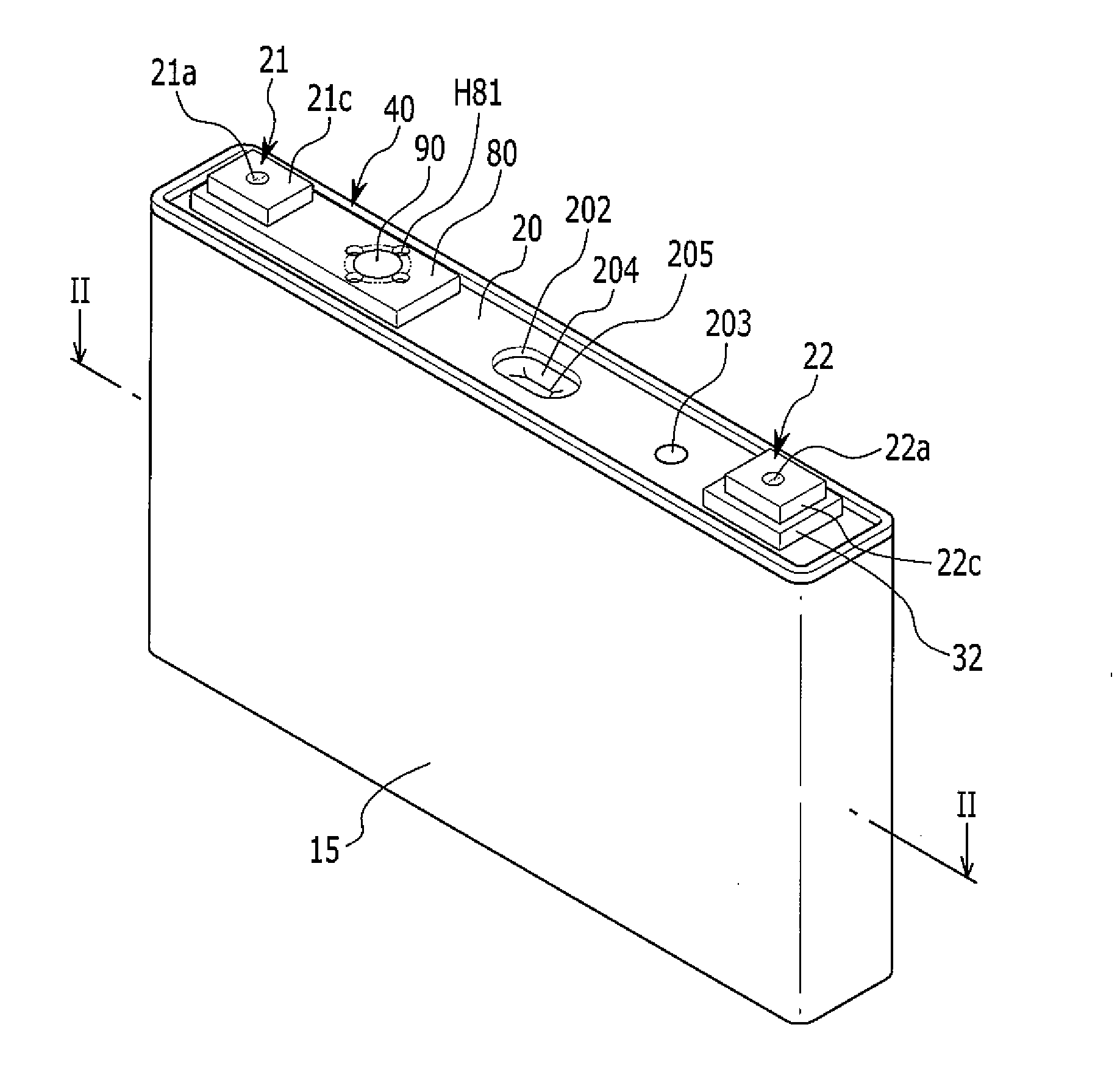
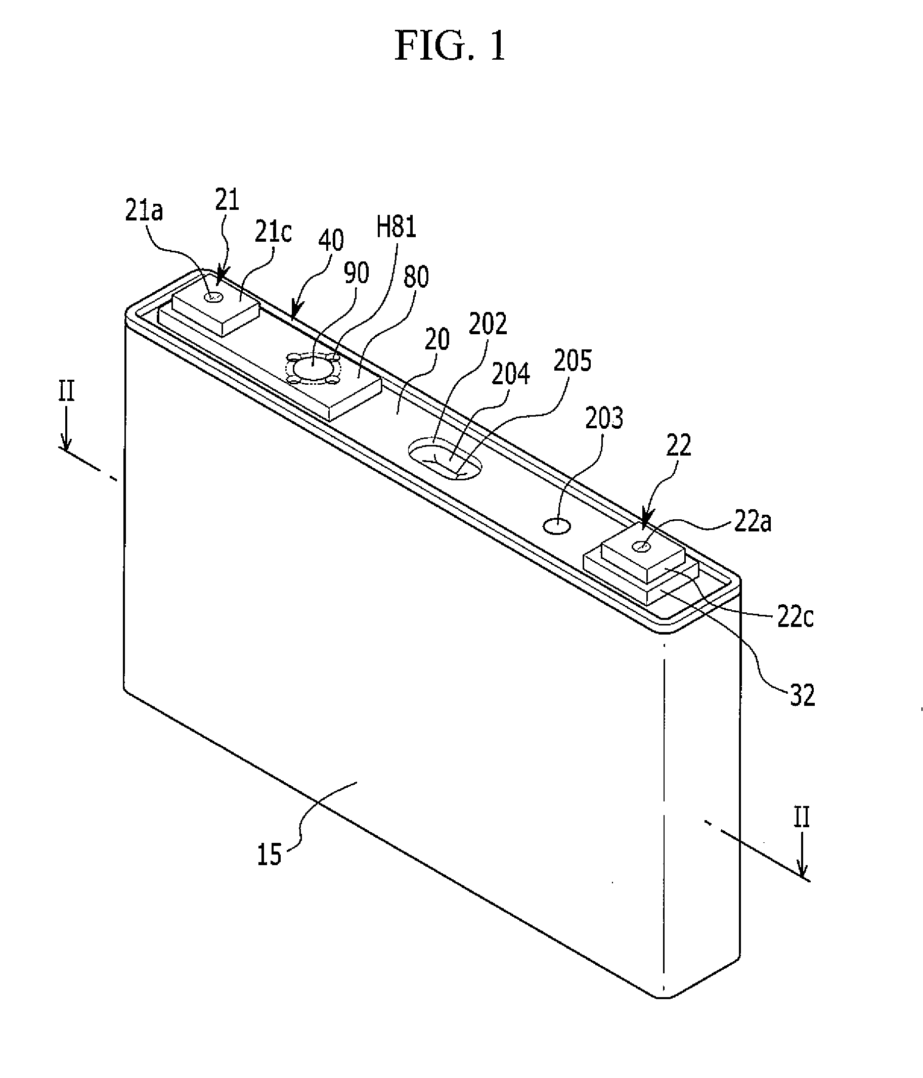
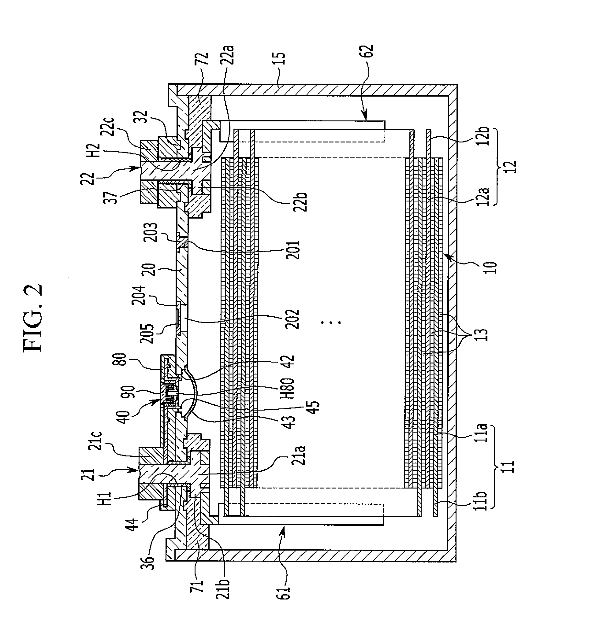
[0043]FIG. 1 is a perspective view of a rechargeable battery according to a first exemplary embodiment of the present invention, and FIG. 2 is a cross-sectional view taken along line II-II of FIG. 1. Referring to FIGS. 1 and 2, a rechargeable battery according to a first exemplary embodiment of the present invention is configured to include an electrode assembly 10 for performing charging and discharging operations, a case 15 having the electrode assembly 10 encl...


PUM


Abstract

A rechargeable battery having a decreased size by including a membrane of an external short-circuit part in a cap plate is provided. The rechargeable battery includes a case having an electrode assembly accommodated therein, a cap plate closing an opening of the case, first and second electrode terminals extending through the cap plate and electrically coupled to the electrode assembly, and an external short-circuit part coupled to an outer portion of the case for electrically disconnecting or short-circuiting the first and second electrode terminals from or to each other. The external short-circuit part includes a membrane coupled to an inner surface of the cap plate and electrically coupled to the second electrode terminal, and a connection plate electrically coupled to the first electrode terminal and spaced from the membrane. The membrane extends around an outer circumference of a short-circuit hole in the cap plate to cover the short-circuit hole.

Description

CROSS-REFERENCE TO RELATED APPLICATION[0001]This application claims priority to and the benefit of Korean Patent Application No. 10-2014-0027901 filed in the Korean Intellectual Property Office on Mar. 10, 2014, the entire contents of which are incorporated herein by reference.BACKGROUND[0002]1. Field[0003]The present invention relates generally to a rechargeable battery having an external short-circuit part.[0004]2. Description of the Related Art[0005]Unlike a primary battery, a rechargeable battery can be repeatedly charged and discharged. A small capacity rechargeable battery may be used in a small portable electronic device such as a mobile phone, a laptop computer, or a camcorder, and a large capacity rechargeable battery may be used, for example, as a power supply for driving a motor of a hybrid vehicle, or the like.[0006]Rechargeable batteries include an electrode assembly including a positive electrode and a negative electrode formed'on respective surfaces of a separator, a ...

Claims


Application Information

Patent Timeline
IPC IPC(8): H01M2/34H01M2/02H01M2/04H01M2/12H01M2/30H01M50/103H01M50/141H01M50/147H01M50/176H01M50/55H01M50/553H01M50/567H01M50/591
CPCH01M2/345H01M2/1235H01M2/30H01M2200/20H01M2/0202H01M2/0237H01M2/0473Y02E60/10H01M50/147H01M50/591H01M50/141H01M50/103H01M50/567H01M50/55H01M50/553H01M50/176H01M50/572H01M50/531H01M10/0431H01M50/578H01M50/15H01M50/342
Inventor GUEN, MIN-HYUNGLEE, CHI-YOUNG
Owner SAMSUNG SDI CO LTD
Learn More