
Method for operating a binaural hearing system and binaural hearing system

a binaural hearing and hearing system technology, applied in the field of hearing devices, can solve the problems of annoying loudness, high sound pressure level, and current monaural techniques for dealing with this problem are only successful to a limited degree, and achieve the effect of improving hearing perception

Active Publication Date: 2015-09-03
SONOVA AG
View PDF3 Cites 21 Cited by
  • Summary
  • Abstract
  • Description
  • Claims
  • Application Information

AI Technical Summary

Benefits of technology

The patent describes a method for reducing wind noise for binaural hearing systems. By analyzing the levels of wind noise at each ear, the method sends a sound signal to the other ear only when there is a significant difference in the level of wind noise between the two ears. This allows the receiving device to replace the sound signal from the exposed ear, which is impacted by wind noise, with the sound signal from the other ear, which is less impacted. Additionally, the method provides options for adjusting the filter parameters based on the user's hearing loss and the vent size of the hearing devices. The method also suggests using an ancillary signal based on certain frequency sub-bands to reduce bandwidth requirements and power consumption. Overall, the method improves the comfort of binaural hearing systems by reducing wind noise and optimizing filter settings.

Problems solved by technology

This phenomenon is known as wind noise and generates high sound pressure levels at the system input, which translate into high output levels at the ear of the user.
This wind noise masks useful signals such as speech and can be annoyingly loud.
Current monaural techniques for dealing with this problem are only successful to a limited degree.
If the gain is reduced also the level of useful signals is lowered and perceived loudness is not kept at the desired level.
If the beamformer is disabled spatial noise reduction is lost.

Method used


Image

  • Method for operating a binaural hearing system and binaural hearing system
  • Method for operating a binaural hearing system and binaural hearing system
  • Method for operating a binaural hearing system and binaural hearing system

Examples


Embodiment Construction

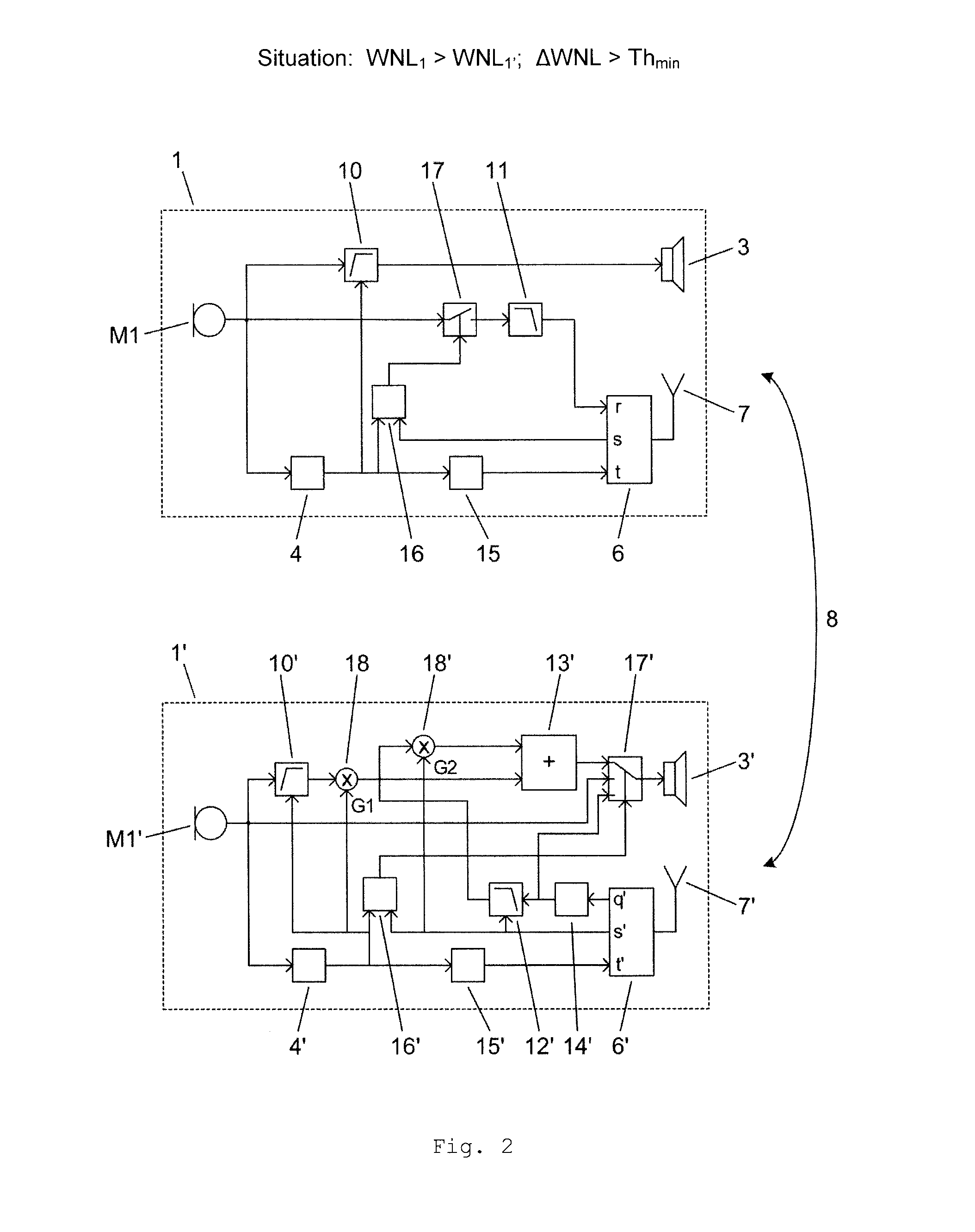
[0062]A basic embodiment of the present invention will now be described with the aid of the schematic illustration presented in FIG. 1. FIG. 1 depicts a high-level block diagram of a binaural hearing system consisting of a first hearing device 1 and a second hearing device 1′ which are interconnected by means of a bidirectional link 8 (also referred to as binaural link). This link commonly is realised as a wireless link, for instance an inductive link or a radio frequency link, but may also be implemented as a wire-bound link or by employing the skin as a conductor. In FIG. 1 the first and second hearing devices 1, 1′ communicate wirelessly using the transceivers 6, 6′ together with the associated antennas 7, 7′. Audio signals (digital or analogue) as well as control data can be exchanged utilising different bandwidths between the two hearing devices 1, 1′ via this link 8. Ambient sound is picked-up separately by each of the first and second hearing devices 1 and 1′ with the corresp...


PUM


Abstract

The present invention proposes a method for operating a binaural hearing system with two hearing devices (1, 1′) operationally interconnected by means of a bidirectional link (8) which improves hearing perception in windy listening situations. The method comprises determining the level of wind noise present at each of the two hearing devices (1, 1′) and sending the audio signal picked-up at the first hearing device (1) to the second hearing device (1′) via the link (8) and then providing an output signal derived from the received signal to the electrical-to-mechanical output converter (3′) of the second hearing device (1′) if the level of wind noise at the second hearing device (1′) exceeds the level of wind noise at the first hearing device (1) by a pre-set threshold value. Furthermore, a binaural hearing system capable of performing such a method is given.

Description

TECHNICAL FIELD[0001]The present invention relates to hearing devices, more specifically to binaural hearing systems comprising two hearing devices, one for each ear of a user. In particular the present invention pertains to a method for coping with wind noise in a binaural hearing system as well as to a binaural hearing system capable of performing such a method.BACKGROUND OF THE INVENTION[0002]Within the context of the present invention a hearing device is a miniature electronic device capable of stimulating a user's hearing and adapted to be worn at an ear or at least partly within an ear canal of a user. A pair of hearing devices, one intended to be worn at the left and the other at the right ear of a user, which are linked to one another is referred to as a binaural hearing system. The link between the two hearing devices of a binaural hearing system allows to bi-directionally exchange control and / or audio signals such as for instance exemplified in WO 99 / 43185 A1 and EP 1 326 ...

Claims


Application Information

Patent Timeline
IPC IPC(8): H04R25/00
CPCH04R2225/41H04R25/552H04R25/407H04R25/554
Inventor KUHNEL, VOLKERDERLETH, RALPH PETERLAMON, RAPHAELREICH, ALEXANDER
Owner SONOVA AG
Learn More