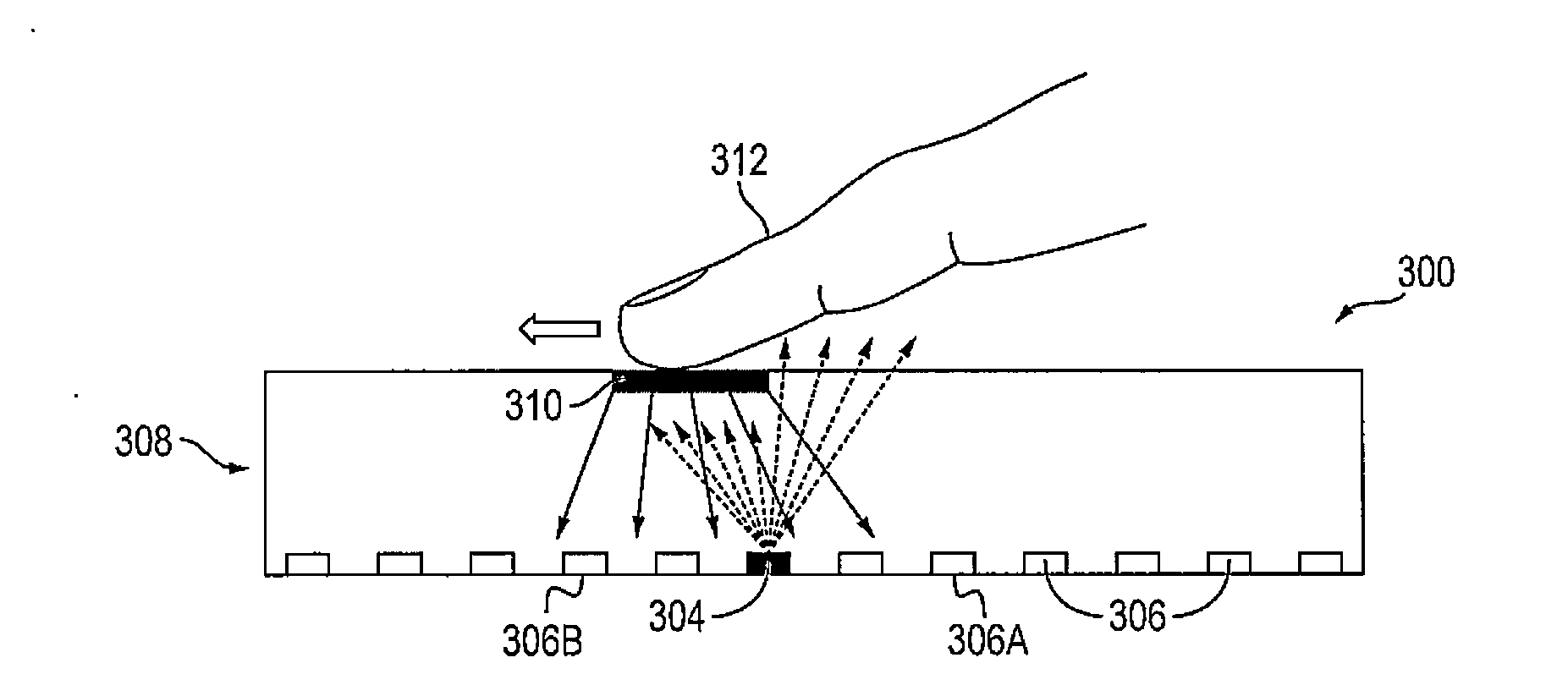
Apparatus and method for detecting surface shear force on a display device

a display device and surface shear force technology, applied in the field of apparatus and methods for detecting surface shear force on display devices, can solve the problems of limited ability of display devices and limited detection ability of display devices, and achieve the effect of practical and inexpensive manufacturing

Active Publication Date: 2015-08-27
SAMSUNG DISPLAY CO LTD
View PDF9 Cites 23 Cited by
  • Summary
  • Abstract
  • Description
  • Claims
  • Application Information

AI Technical Summary

Benefits of technology

[0008]Aspects of embodiments of the present invention are directed toward a display device that is capable of sensing a shear force interaction with the display device by a user that is also practical and inexpensive to manufacture.
[0009]Embodiments of the present invention provide a display device that has an increased capability of sensing various user gestures.

Problems solved by technology

However, although display devices are able to detect a position of a user interaction (e.g., a user's touch), display devices have been limited in the ability to detect pressure of a touch interaction by the user.
In particular, display devices are limited in the ability to sense a shear force (or shearing force) exerted by a user upon the display device.

Method used


Image

  • Apparatus and method for detecting surface shear force on a display device
  • Apparatus and method for detecting surface shear force on a display device
  • Apparatus and method for detecting surface shear force on a display device

Examples


Embodiment Construction

[0046]Hereinafter, embodiments of the present invention will be described more fully with reference to the accompanying drawings, in which example embodiments of the present invention are shown. As those skilled in the art would realize, the described embodiments are susceptible to various modifications and alternative forms without departing from the spirit or scope of the present invention. For clarity of the description of the present invention, some elements or features not required for the complete understanding of the present invention may be omitted.

[0047]The terms used in the present specification are used to describe particular embodiments, and are not intended to limit the present invention. For example, it will be understood that, although the terms “first,”“second,” etc., may be used herein to describe various elements, these elements would not be limited by the strict construction of these terms. Instead, these terms are used only to distinguish one component from anoth...


PUM


Abstract

A display device includes: a pixel array including a plurality of pixels; a plurality of infrared (IR) emitters to emit IR light towards a surface of the display device; a plurality of IR detectors to detect IR light; a deformable layer on the pixels, on the IR emitters, on the IR detectors, and at the surface of the display device; and a plurality of tracers at the deformable layer to reflect the IR light emitted by the IR emitters towards the IR detectors and to, while a shear force is being applied at a point of contact at the surface of the display device, shift ones of the tracers around the point of contact in a direction of the shear force such that IR reflectance at the surface of the display device is changed.

Description

CROSS-REFERENCE TO RELATED APPLICATION(S)[0001]The present application claims priority to and the benefit of U.S. Provisional Application No. 61 / 945,743, filed Feb. 27, 2014, entitled “DISPLAY OPTICAL SHEAR DETECTION SYSTEM,” the entire content of which is incorporated herein by reference in its entirety.BACKGROUND[0002]1. Field[0003]Embodiments of the present invention relate to an apparatus and method for detecting surface shear force on a display device.[0004]2. Related Art[0005]Display devices have become increasingly popular and are widely used, such as in cell phones, computer monitors, televisions, tablets, etc. These display devices may be any type of display, including an organic light emitting display (OLED), a liquid crystal display (LCD), etc. In particular, display devices including optical sensors have been developed, for example, to detect a user's interaction with the display device (e.g., an interaction with the display device via the user's finger or via the user's...

Claims


Application Information

Patent Timeline
Patent Type & Authority Applications(United States)
IPC IPC(8): G06F3/042G06F3/041
CPCG06F3/0428G06F3/0416G06F2203/04106G06F2203/04109G06F3/0412G06F3/0421
Inventor HOFFMAN, DAVID M.
Owner SAMSUNG DISPLAY CO LTD
Why Eureka
Try Eureka