
Method and Mobile Communication Appliance for Selecting a Transmission Path

a mobile communication and transmission path technology, applied in the direction of location information based service, wireless communication, assessment restriction, etc., can solve the problems of many cases unnecessarily high cost, achieve high utilization level, avoid bottlenecks, and control the utilization level of individual connecting paths

Active Publication Date: 2015-08-20
UNIFY PATENTE GMBH & CO KG
View PDF4 Cites 0 Cited by
  • Summary
  • Abstract
  • Description
  • Claims
  • Application Information

AI Technical Summary

Benefits of technology

[0015]In this case, the database may be stored in the communication appliance itself, which means that access to the database is particularly rapid and simple, and it is a simple matter to prevent manipulation of the database by third parties. On the other hand, a database which is available centrally in a communication network may also be used for this purpose, which means that a communication appliance can also use the empirical values and rules (routing rules) from other communication appliances. Finally, the parallel use of both a local and a central database is also advantageous in many cases, because it firstly allows redundancy requirements to be met, and secondly allows “one's own” entries to be used preferably, in order to be able to resort to the centrally stored entries if such entries “of one's own” are not present.
[0017]The data obtained through the continuous and automatic “care” of the entries in the database may advantageously also be used for optimizing a radio network to which an associated transmission path belongs. It is therefore possible in many cases to dispense with the separate measurement of radio areas and nevertheless to obtain a constantly up-to-date overview of radio ranges, “radio holes”, field strength distributions or the like. In this case, it is also possible for a central location (for example a system administrator) to make changes in the data records in the database such that future selection decisions are influenced. This makes it possible to control the utilization level of individual connecting paths and to avoid bottlenecks.
[0018]If a time statement about the time and / or the time of day and / or a day-of-week statement is used to select the transmission path, the database providing statistical statements about the quality of at least one transmission path for a particular time and / or time of day and / or day of the week, it is also possible to take account of changes on the transmission paths which are recurrent on the basis of time. By way of example, this involves taking account of cases in which particular transmission paths (for example a company WLAN) have a high utilization level at particular times of day (for example during normal business hours) and therefore provide reduced bandwidth.
[0019]Manual input of location information into a communication appliance is avoided if the statement about the location of the communication appliance is ascertained using a satellite-assisted position-finding system (e.g. “GPS”) and / or a method for position-finding using received terrestrial radio base stations (field strength and / or propagation-time measurements).

Problems solved by technology

In the case of the known methods and devices for selecting one of a plurality of transmission paths, it is found to be disadvantageous that the selected transmission path in many cases does not assure the required transmission quality, and / or although a high-quality transmission path is selected it is in many cases unnecessarily expensive.

Method used


Image

  • Method and Mobile Communication Appliance for Selecting a Transmission Path
  • Method and Mobile Communication Appliance for Selecting a Transmission Path

Examples


Embodiment Construction

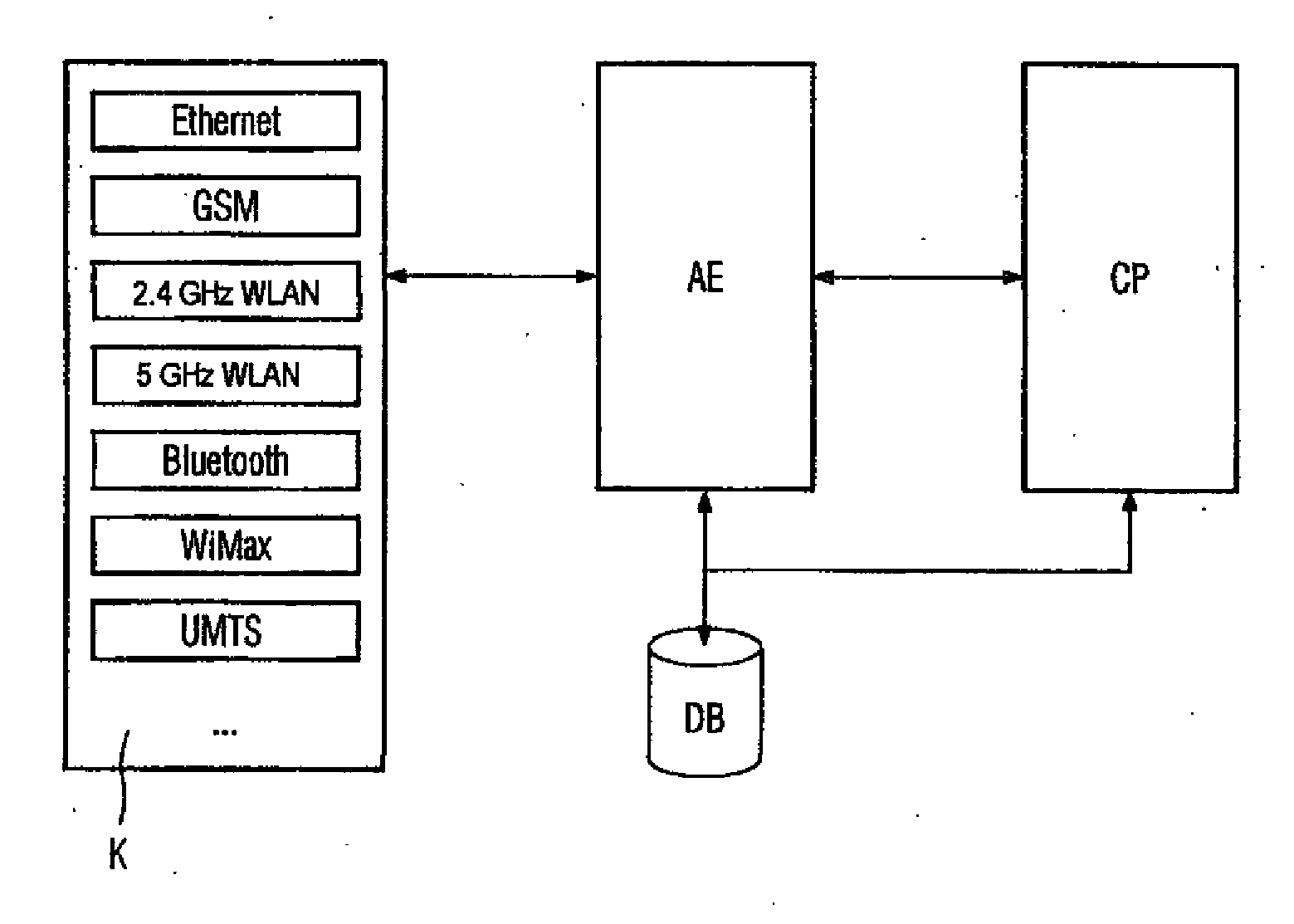
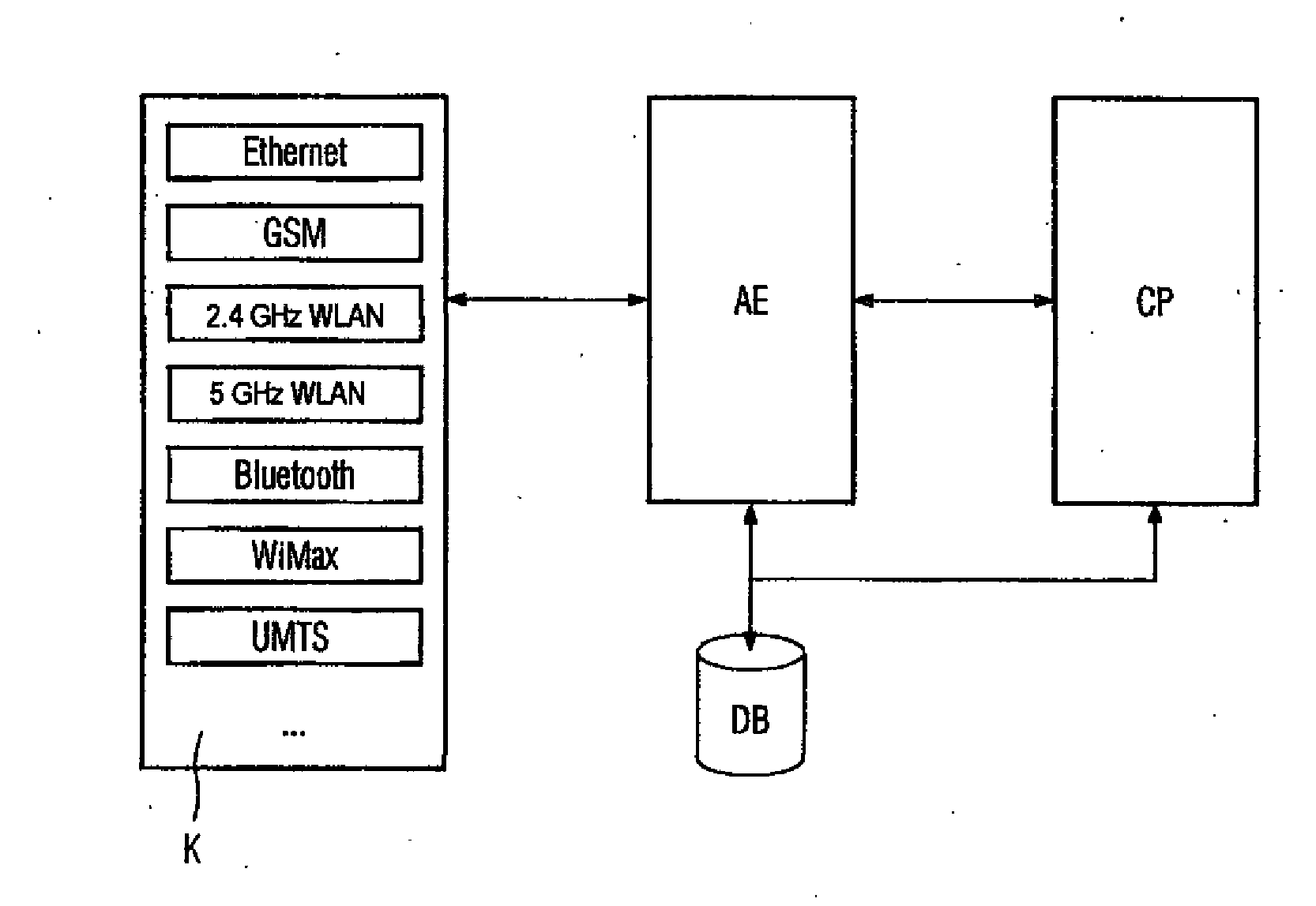
[0023]The FIGURE shows a schematic illustration of components of a mobile communication appliance. In this case, the mobile communication appliance is what is known as a “smart phone”, that is to say an appliance in which the functions of a mobile computer (“PDA”—Personal Digital Assistant) and the functions of a mobile radio (mobile telephone) are combined with one another. The communication appliance is in multimodal form, that is to say has access units K (connectors) for various radio networks, in this case GSM, WLAN, Bluetooth, WiMax, UMTS, etc. In addition, the communication appliance also has access units K for wired communication; for this, the FIGURE shows an Ethernet access unit by way of example.

[0024]The text below—unless a different description is given—simply assumes that each access unit K is associated with precisely one transmission method (GSM, Internet Protocol, ISDN . . . ), which means that the access units K in the FIGURE simultaneously represent transmission m...


PUM


Abstract

There is described a method for selecting a transmission path for a communication connection of a mobile communication device, wherein at least two transmission paths can be selected by the mobile communication device. In a first step, an option is determined via the position of the communication device, in a second step, the option is accessed using the determined option on the data bank for the transmission path, in a third step, a preferred transmission path is determined using at least one entry of the data bank, and in a fourth step, the preferred transmission path is selected and used for the communication connection.

Description

CROSS REFERENCE TO RELATED APPLICATIONS[0001]This application is the US National Stage of International Application No. PCT / EP2006 / 063162, filed Jun. 13, 2006 and claims the benefit thereof. The International Application claims the benefits of German application No. 10 2005 030 796.5 DE filed Jun. 29, 2005, both of the applications are incorporated by reference herein in their entirety.FIELD OF INVENTION[0002]The invention relates to a method for a mobile communication appliance and to a communication terminal for wirelessly accessing a plurality of transmission paths.BACKGROUND OF INVENTION[0003]There are frequently various radio-based voice networks and data networks available for mobile communication links. In this context, the radio-based voice networks, that is to say GSM networks, DECT networks and UMTS networks, for example, can also be used for data transmission, as can, conversely, radio-based data networks, that is to say WLAN networks, WiMax networks and Bluetooth network...

Claims


Application Information

Patent Timeline
Patent Type & Authority Applications(United States)
IPC IPC(8): H04W48/18H04W72/08H04W4/02
CPCH04W48/18H04W72/08H04W4/025H04W72/54
Inventor LUERS, JURGEN
Owner UNIFY PATENTE GMBH & CO KG
Learn More