
Liquid chromatograph and column oven for use therein

a column oven and liquid chromatograph technology, which is applied in the field of liquid chromatographs, can solve the problems of leakage of vaporized gas generated by the mobile phase, and achieve the effect of eliminating false detection of liquid leakag

Active Publication Date: 2015-08-20
SHIMADZU CORP
View PDF7 Cites 4 Cited by
  • Summary
  • Abstract
  • Description
  • Claims
  • Application Information

AI Technical Summary

Benefits of technology

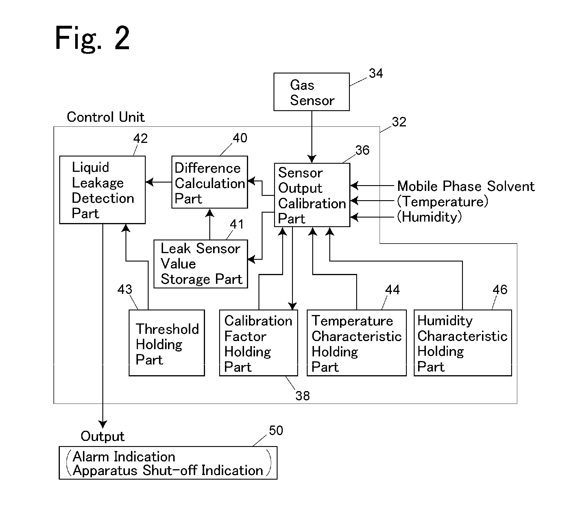
The present invention provides a method for accurately detecting liquid leakage in a column oven without being affected by changes in the gas sensor's sensitivity over time. This is achieved by measuring the change in leak sensor value over a very short period of time (the amount of change per very short period of time is insignificant) and performing a calibration to obtain a reference value (the first calibration factor) for the gas sensor. This reference value is then used to calibrate the gas sensor's output signal to obtain the leak sensor value. By setting a threshold to a value greater than the amount of change in the leak sensor value caused by a temporal change in the sensitivity of the gas sensor, false detection of liquid leakage caused by a temporal change in the gas sensor is avoided.

Problems solved by technology

When the mobile phase includes a volatile solvent, vaporized gas is generated from the mobile phase leaked.
It has been noticed that a system that monitors a leak sensor value based on an output of the gas sensor, and which detects leakage of a mobile phase solvent by comparing the leak sensor value with a leakage threshold as described above poses a problem in that a prolonged continuous operation of a column oven may cause a false detection of liquid leakage even when no leakage of the mobile phase solvent is present.
Moreover, since the sensitivity of a gas sensor also depends on temperature and humidity, a temporal change in the temperature and / or humidity around the gas sensor may cause the leak sensor value to vary, which may also cause a false detection of liquid leakage.

Method used


Image

  • Liquid chromatograph and column oven for use therein
  • Liquid chromatograph and column oven for use therein
  • Liquid chromatograph and column oven for use therein

Examples


Embodiment Construction

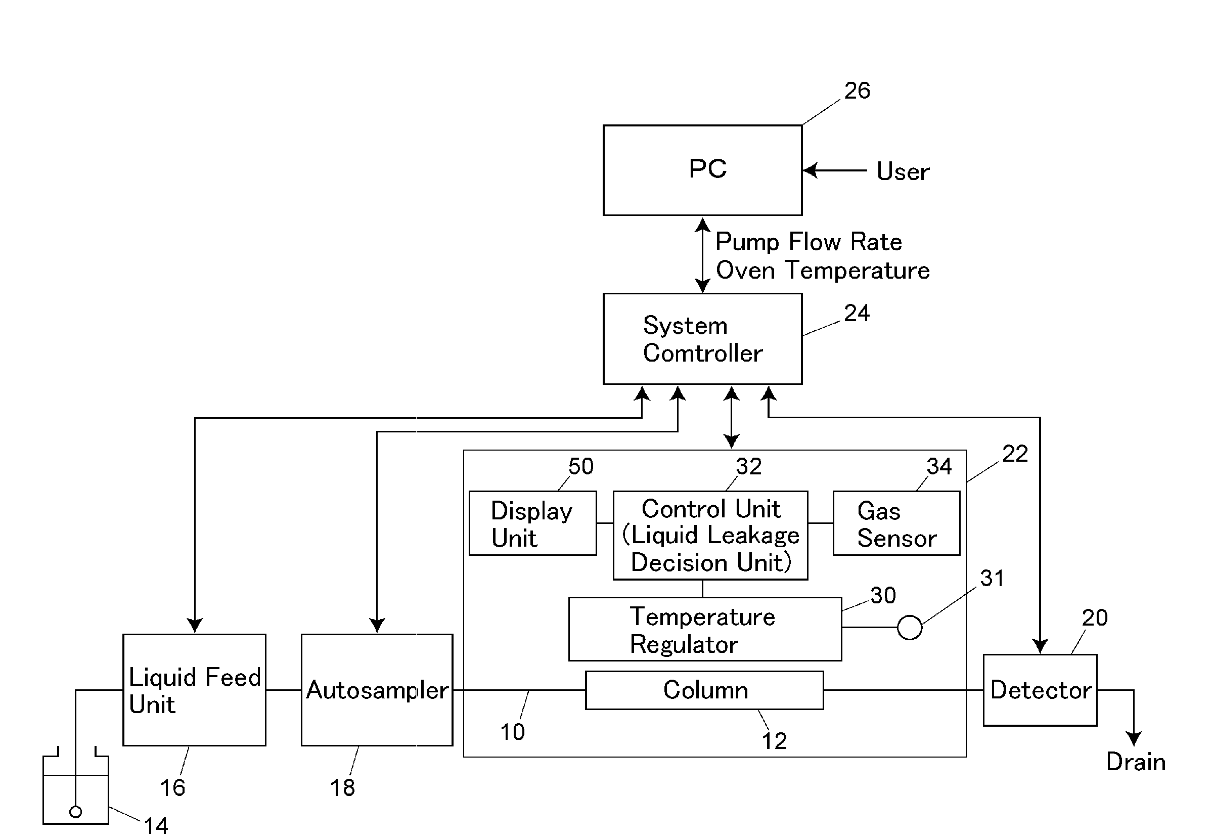
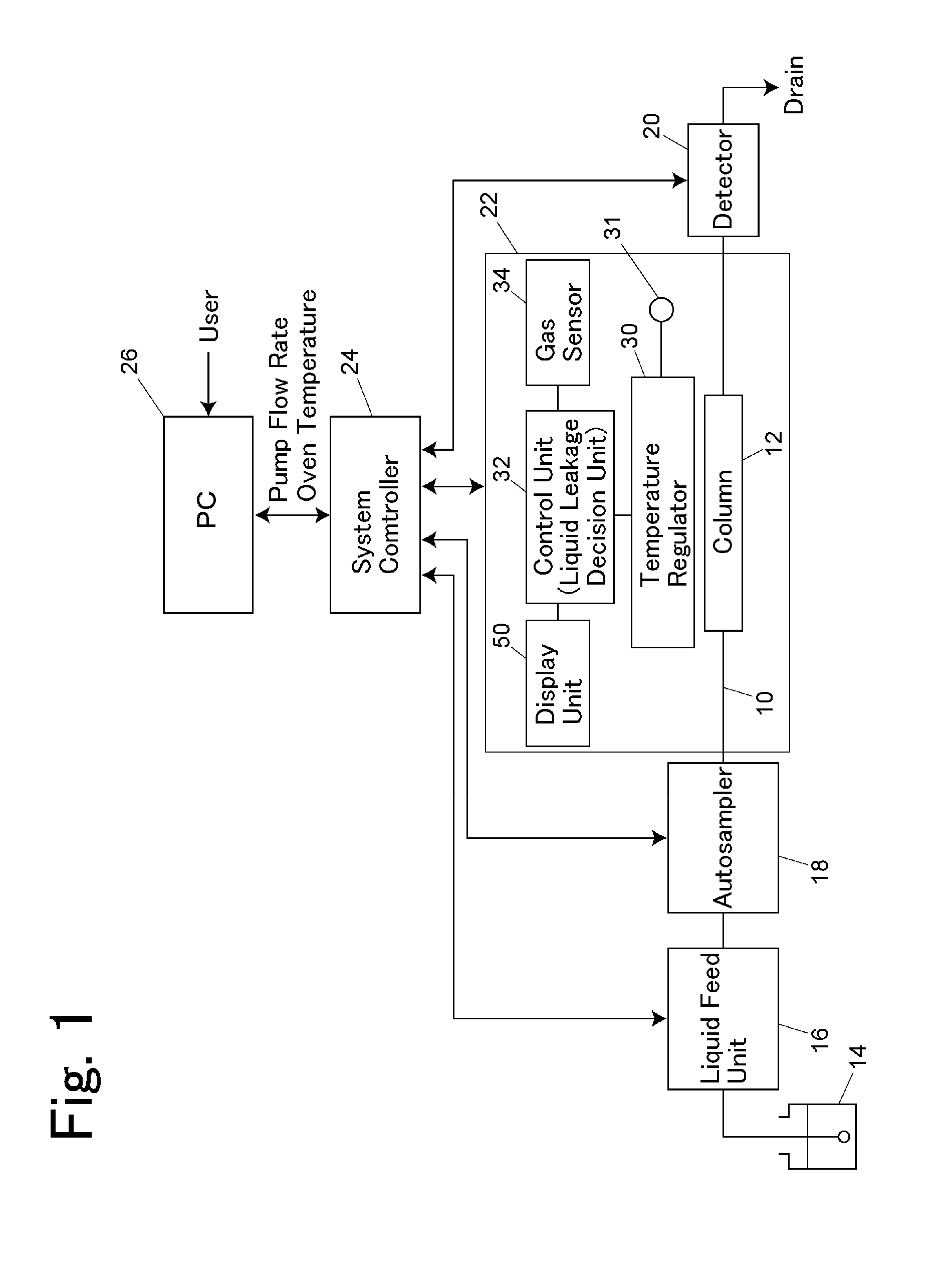
[0032]FIG. 1 illustrates a liquid chromatograph of one embodiment. In order to feed a mobile phase 14 to an analysis channel 10 provided with a separation column 12, a liquid feeder 16 is provided most upstream. As one example of the liquid feeder 16, a liquid feed unit is used which is configured to independently function by means of a liquid feed pump. The liquid feed unit 16 is connected to a system controller 24, and the liquid feed operation on the mobile phase is controlled according to a condition set in the system controller 24.

[0033]A sample injector 18 is provided in the analysis channel 10 between the liquid feed unit 16 and the separation column 12 in order to inject a sample into the analysis channel 10 containing the mobile phase 14 fed thereto. As one example of the sample injector 18, an autosampler 18 is used. The autosampler 18, also, is connected to the system controller 24, and injects, into the analysis channel 10, a specified amount of the sample set in the sys...


PUM


Abstract

A liquid leakage decision unit includes a leak sensor value storage part that stores a leak sensor value that is based on the intensity of a signal received from a gas sensor; a difference calculation part that, when the signal is received from the gas sensor, calculates, as a difference value, a value obtained by subtracting a previous leak sensor value stored in the leak sensor value storage part from a current leak sensor value; and a liquid leakage detection part that compares the difference value calculated by the difference calculation part with a preset threshold, thereby to detect liquid leakage in the column oven.

Description

BACKGROUND OF THE INVENTION[0001]1. Field of the Invention[0002]The present invention relates to a liquid chromatograph including a high performance liquid chromatograph, and to a column oven for use therein.[0003]2. Description of the Related Art[0004]A liquid chromatograph performs separation analysis while maintaining the separation column at a constant temperature. In order to hold the column temperature constant, the separation column is placed in a column oven. The column oven includes a temperature regulator for maintaining the column oven at a constant temperature. The temperature regulator includes, for example, a block heater as a heat source, and employs an air circulation method for circulating its heat in the column.[0005]The mobile phase of a liquid chromatograph may be a volatile solvent such as methanol, acetonitrile, or isopropyl alcohol (IPA). The separation column is connected to the analysis channel by means of a joint in the column oven, and the mobile phase may...

Claims


Application Information

Patent Timeline
IPC IPC(8): G01N30/30G01N30/16
CPCG01N30/30G01N2030/3084G01N2030/027G01N30/16G01N30/24G01N30/88G01N2030/8804G01M3/16
Inventor TAKAHASHI, KAZUYAIWATA, YOSUKE
Owner SHIMADZU CORP
Learn More