
Scoring Machine

a scoring machine and scoring technology, applied in the field of scoring machines, can solve the problems of misalignment of folding lines, dull folding lines, possible causes of scoring machines, etc., and achieve the effect of short time, simplified and downsized scoring machines, and downsizing the buckle-type sheet folding apparatus

Active Publication Date: 2015-08-20
HORIZON INTERNATIONAL INC
View PDF1 Cites 1 Cited by
  • Summary
  • Abstract
  • Description
  • Claims
  • Application Information

AI Technical Summary

Benefits of technology

The present invention simplifies the positioning of rollers in a scoring machine by using a single positioning unit to position all rollers on one of the upper and lower rotary shafts. This simplifies the mechanics of the scoring machine and reduces the size of the machine, allowing it to be incorporated into a buckle-type sheet folding apparatus. The positioning of the rollers is easy and quick, and all rollers can be positioned on one shaft. This reduces the size of the entire scoring machine and makes it more portable and user-friendly.

Problems solved by technology

In such cases, the sheets increase their thickness and stiffness by being folded like an accordion by the first (upstream) buckle-type sheet folding apparatus and, if the accordion-folded sheets are directly fed from the first buckle-type sheet folding apparatus to the second (downstream) buckle-type sheet folding apparatus, the misalignment of folding lines and dull folding lines and so on are possibly caused.
Consequently, the scoring machine has a defect that its size becomes bigger and its structure is complicated.

Method used


Image

  • Scoring Machine
  • Scoring Machine
  • Scoring Machine

Examples


Embodiment Construction

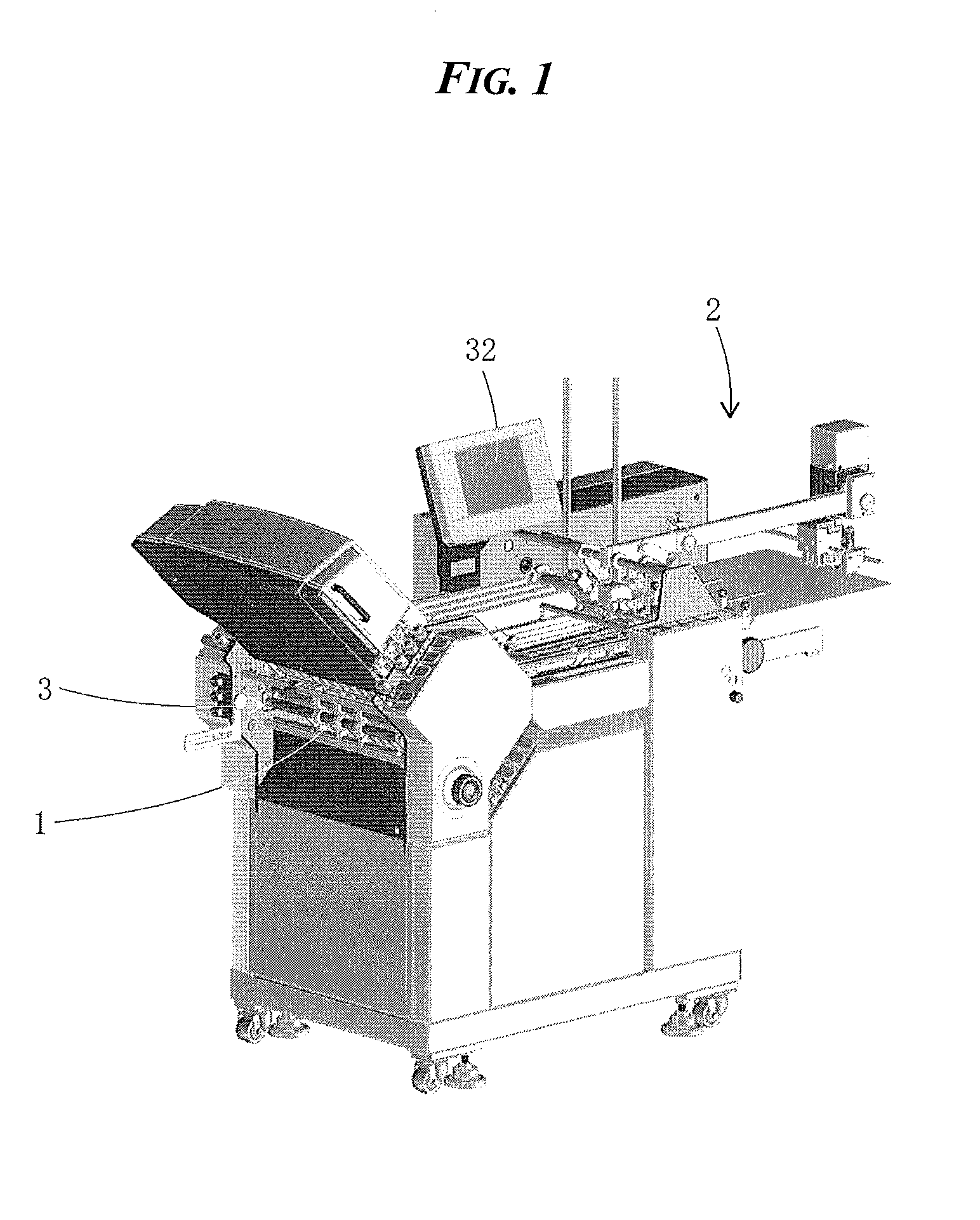
[0030]A preferred embodiment of the present invention will be explained below with reference to accompanying drawings. In this embodiment, as shown in FIG. 1, a scoring machine 1 according to the present invention is incorporated in a sheet outlet 3 of a buckle-type sheet folding apparatus 2. Although not shown in FIG. 1, another buckle-type sheet folding apparatus is connected to the sheet outlet 3 of the buckle-type sheet folding apparatus 2 so as to be arranged perpendicularly to a sheet ejecting direction of the buckle-type sheet folding apparatus 2. Then the sheet folded by the buckle-type sheet folding apparatus 2 is further folded by the downstream buckle-type sheet folding apparatus in a predetermined folding pattern perpendicularly to the direction of folds provided by the buckle-type sheet folding apparatus 2.

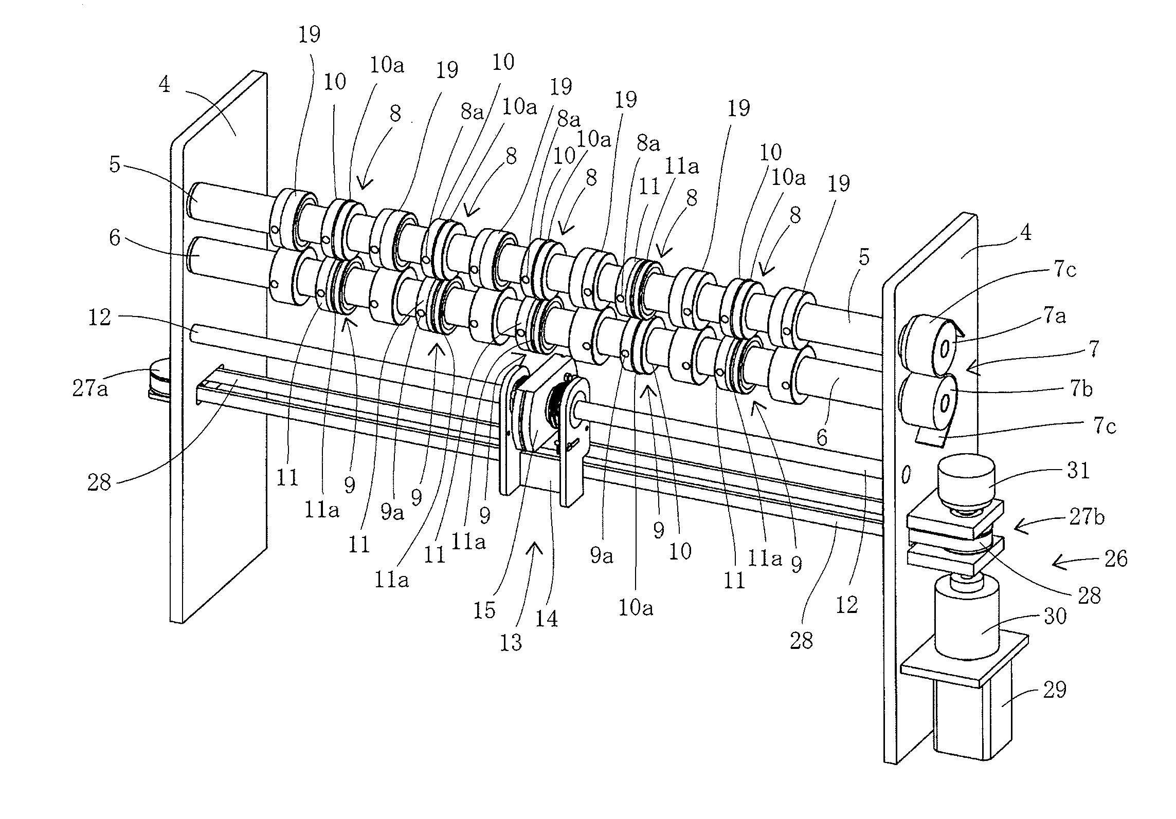
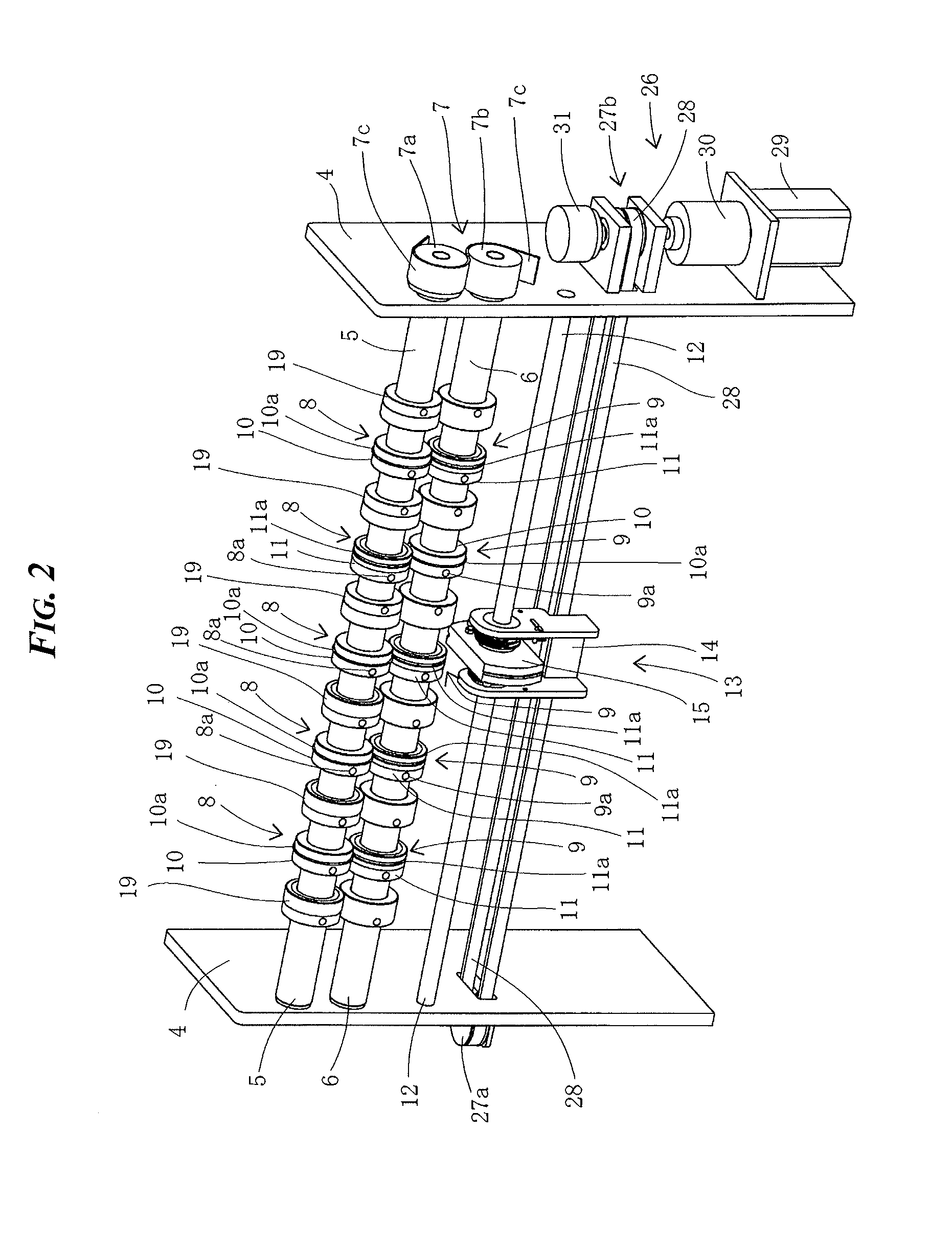
[0031]FIG. 2 is a schematic perspective view of the scoring machine shown in FIG. 1. Referring to FIG. 2, the scoring machine 1 has a frame 4. Horizontal upper and lo...


PUM

PropertyMeasurementUnit
distanceaaaaaaaaaa
distance measurementaaaaaaaaaa
travel distanceaaaaaaaaaa

Abstract

Pairs of convex and concave rollers 10, 11 are mounted on upper and lower rotary shafts 8, 9. A positioning unit 13 is slidably attached to a slide guide 12. When a rotatable member 15 is arranged at a standing position, an annular projection 10a of the convex roller engages with a groove on one end face of the rotatable member, or an annular groove 11a of the concave roller 11 engages with a projection on the other end face of the rotatable member. The positioning unit slides while stopping at the specified positions of the roller pairs.

Description

TECHNICAL FIELD[0001]The present invention relates to a scoring machine incorporated in a buckle-type sheet folding apparatus so as to form a score or scores on sheets according to a folding pattern achieved by the sheet folding apparatus.BACKGROUND ART[0002]The buckle-type sheet folding apparatus has a plurality of buckles into which sheets to be folded are inserted by a length corresponding to a predetermined folding position. In each of the buckles, a stopper whose position is adjustable is arranged so that the sheet is stopped by colliding its leading end with the stopper so as to be set at the folding position. At an inlet of each of the buckles, a pair of driven intake rollers is arranged opposite to each other so as to take the sheet into the associated buckle and a pair of driven discharge rollers is arranged opposite to each other so as to fold a portion of the sheet deflected from the associated buckle outward.[0003]Then the sheet is fed to the buckle-type sheet folding ap...

Claims


Application Information

Patent Timeline
Patent Type & Authority Applications(United States)
IPC IPC(8): B31F1/00
CPCB31F1/0025B65H45/30
Inventor WATANABE, SHINYAIDA, TATSUAKI
Owner HORIZON INTERNATIONAL INC
Learn More