
Pixilated temperature controlled substrate support assembly

a temperature controlled substrate and support assembly technology, applied in the field of semiconductor manufacturing, can solve the problems of difficult to achieve the allowable cd variation across the substrate processed within the processing chamber, difficult to achieve uniform temperature control across and difficult to achieve the uniformity of processing results along the surface of the substra

Active Publication Date: 2015-08-13
APPLIED MATERIALS INC
View PDF14 Cites 240 Cited by
  • Summary
  • Abstract
  • Description
  • Claims
  • Application Information

AI Technical Summary

Benefits of technology

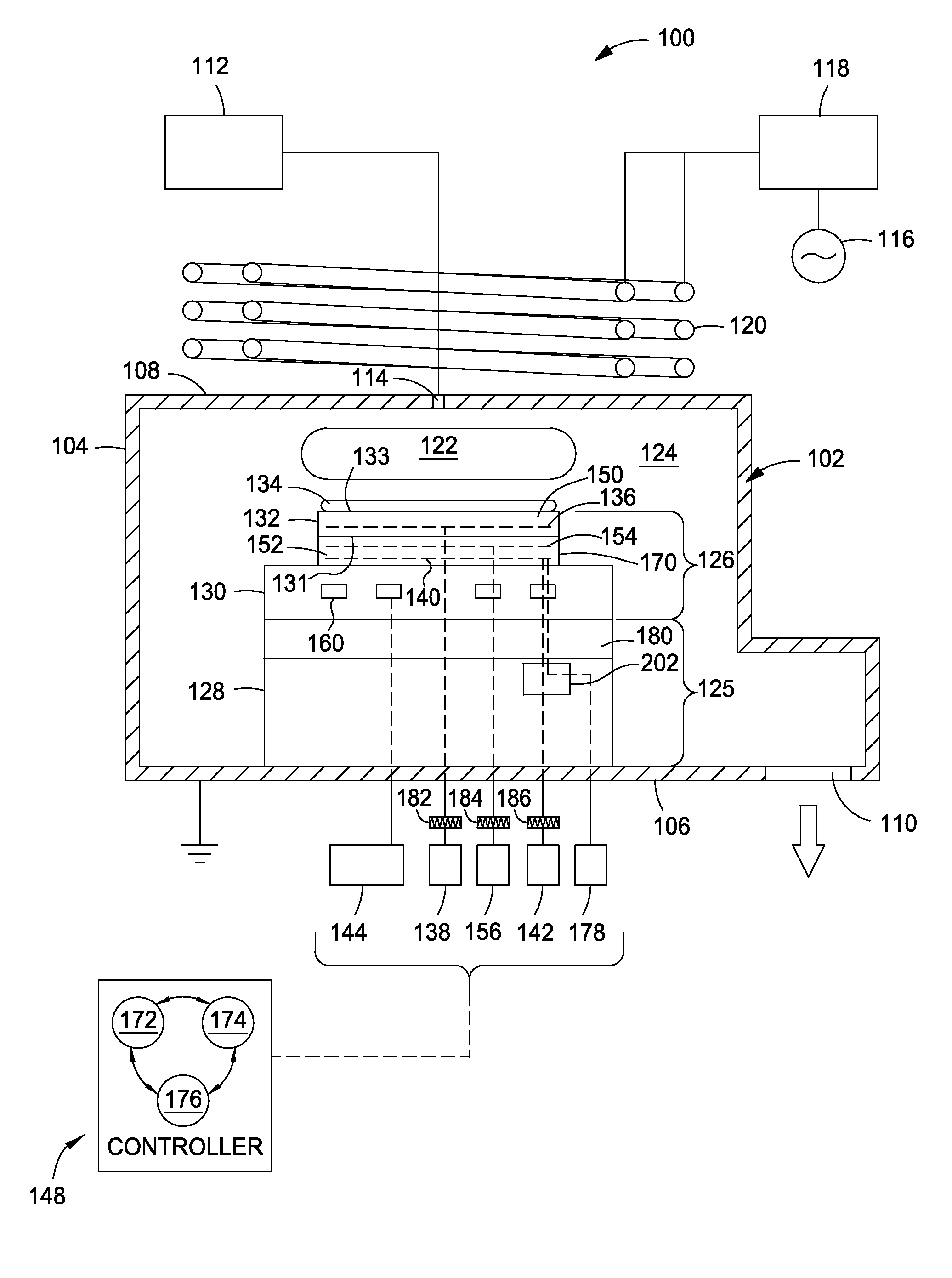
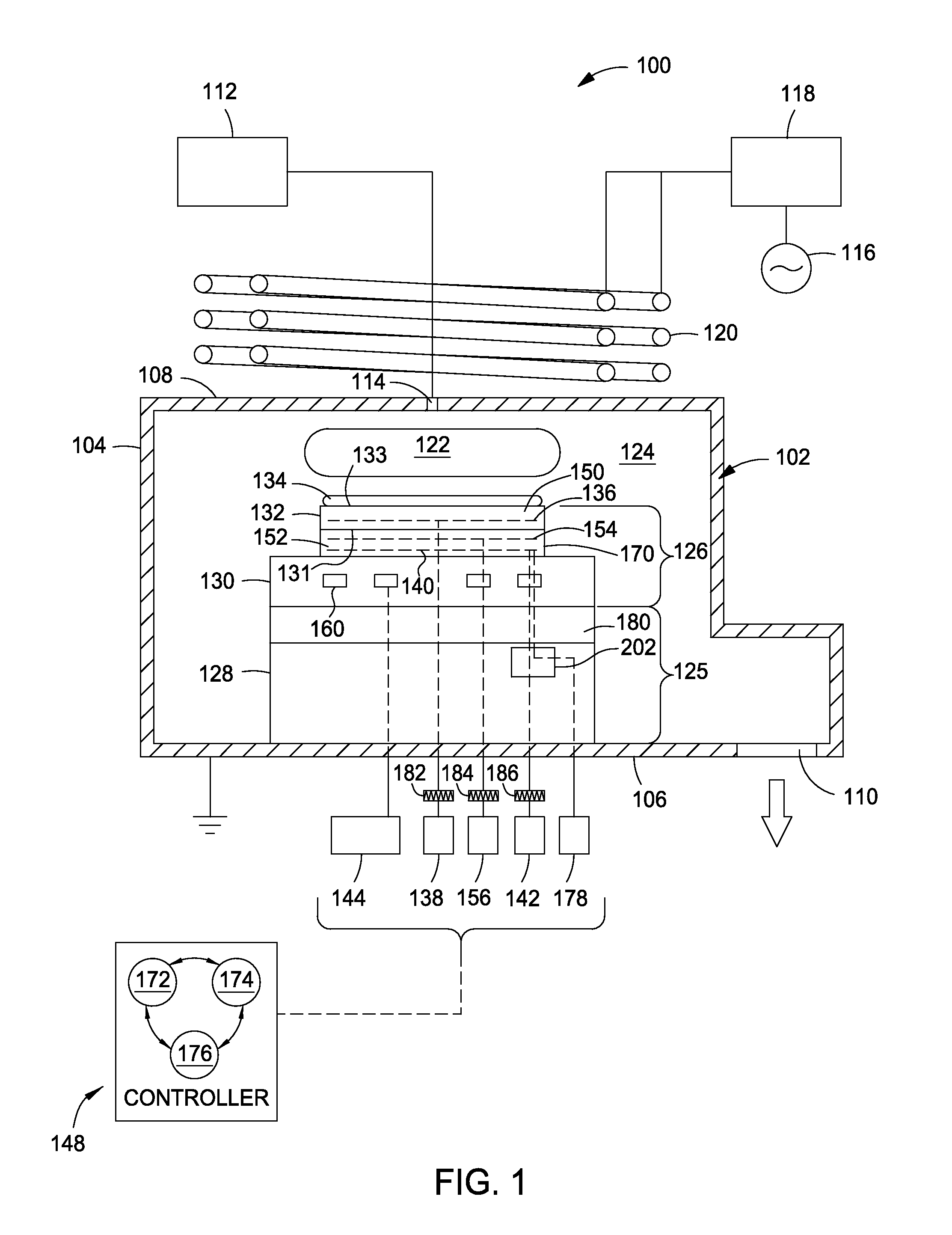
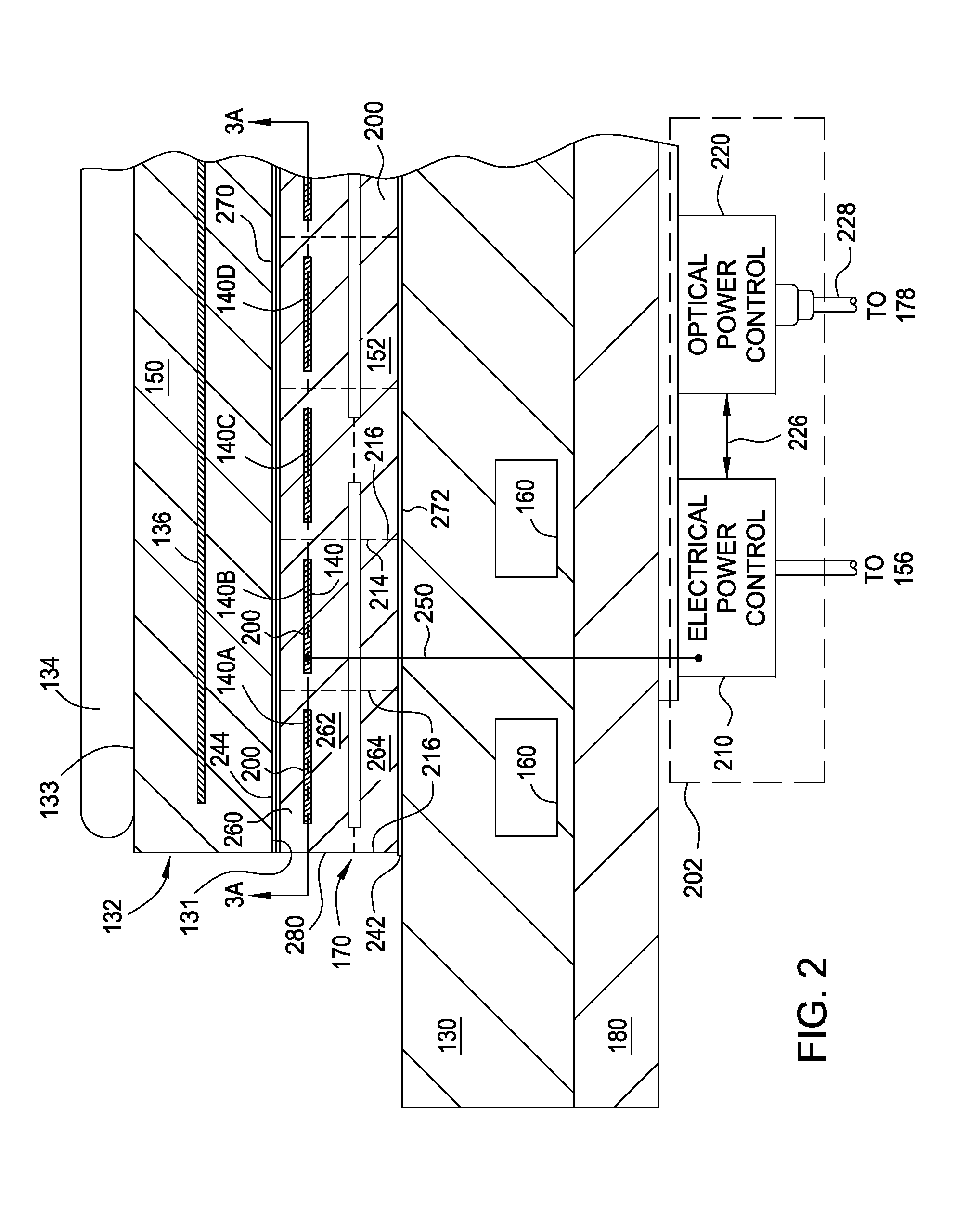
The patent text describes a substrate support assembly for a processing chamber that allows for both lateral and azimuthal tuning of heat transfer between an electrostatic chuck and a heating assembly. The assembly includes one or more main resistive heaters and a plurality of pixel heaters that are independently controllable relative to each other and the main resistive heaters. The pixel heaters are significantly more numerous than the main resistive heaters and are arranged in columns. The technical effect of this invention is that it provides better heat transfer control and uniformity for processing substrates in a processing chamber.

Problems solved by technology

Allowable CD variation across a substrate processed within a processing chamber is difficult to achieve due to chamber asymmetries such as chamber and substrate temperature, flow conductance, and RF fields.
In processes utilizing an electrostatic chuck, uniformity of temperature control across the surface of the substrate is even more challenging due to the non-homogeneous construction of the chuck below the substrate.
Since the structure of the electrostatic chuck can vary both laterally and azimuthally, uniformity of heat transfer between the chuck and substrate is complicated and very difficult to obtain, resulting in local hot and cold spots across the chuck surface, which consequently result in non-uniformity of processing results along the surface of the substrate.
The lateral and azimuthal uniformity of heat transfer between the chuck and substrate is further complicated by heat transfer schemes commonly utilized in conventional substrate supports to which the electrostatic chuck is mounted.
Thus, local hot and cold spots within the electrostatic chuck cannot be compensated for while utilizing the heat transfer features of the conventional substrate supports.

Method used


Image

  • Pixilated temperature controlled substrate support assembly
  • Pixilated temperature controlled substrate support assembly
  • Pixilated temperature controlled substrate support assembly

Examples


example 1

[0108]A processing chamber comprising:

[0109]chamber body;

[0110]a pixilated substrate support assembly, comprising:

[0111]an upper surface and a lower surface;

[0112]one or more main resistive heaters disposed in the pixilated substrate support assembly; and

[0113]a plurality of pixel heaters in column with the main resistive heaters and disposed in the pixilated substrate support, wherein a quantity of the pixel heaters is an order of magnitude greater than a quantity of the main resistive heaters and the pixel heaters are independently controllable relative to each other as well as the main resistive heaters.

example 2

[0114]The processing chamber of example 1, wherein the pixilated substrate support is an electrostatic chuck.

example 3

[0115]The processing chamber of example 1, wherein electrostatic chuck has a ceramic body.


PUM


Abstract

Implementations described herein provide a pixilated substrate support assembly which enables both lateral and azimuthal tuning of the heat transfer between an electrostatic chuck and a heating assembly. The pixilated substrate support assembly comprises an upper surface and a lower surface; one or more main resistive heaters disposed in the pixilated substrate support; and a plurality of pixel heaters in column with the main resistive heaters and disposed in the substrate support. A quantity of the pixel heaters is an order of magnitude greater than a quantity of the main resistive heaters and the pixel heaters are independently controllable relative to each other as well as the main resistive heater.

Description

CROSS-REFERENCE TO RELATED APPLICATIONS[0001]This application claims benefit of U.S. Provisional Application Ser. No. 61 / 937,348, filed Feb. 7, 2014 (Attorney Docket No. APPM / 21606USL), of which is incorporated by reference in its entirety.BACKGROUND[0002]1. Field[0003]Implementations described herein generally relate to semiconductor manufacturing and more particularly to temperature controlled substrate support assembly and method of using the same.[0004]2. Description of the Related Art[0005]As the feature size of the device patterns get smaller, the critical dimension (CD) requirements of these features become a more important criterion for stable and repeatable device performance. Allowable CD variation across a substrate processed within a processing chamber is difficult to achieve due to chamber asymmetries such as chamber and substrate temperature, flow conductance, and RF fields.[0006]In processes utilizing an electrostatic chuck, uniformity of temperature control across th...

Claims


Application Information

Patent Timeline
Patent Type & Authority Applications(United States)
IPC IPC(8): H01L21/67H01L21/683
CPCH01L21/67103H01L21/6833H01L21/67248H01L21/6831H01L21/324H01L21/67098H01L21/6835
Inventor PARKHE, VIJAY D.MAKHRATCHEV, KONSTANTINONO, MASANORIGUO, ZHIQIANG
Owner APPLIED MATERIALS INC
Learn More