
Electric valve and refrigerating system comprising the same

a technology of electric valves and refrigerating systems, which is applied in the direction of valve operating means/release devices, refrigeration components, light and heating apparatus, etc., can solve the problems of more energy dissipation, more energy loss, and meaningless energy dissipation of refrigerators, so as to improve the stability of the refrigerating system, energy saving, and effective reduction of energy dissipation in the refrigerating system

Active Publication Date: 2015-08-13
CHANGHONG MEILING CO LTD
View PDF5 Cites 4 Cited by
  • Summary
  • Abstract
  • Description
  • Claims
  • Application Information

AI Technical Summary

Benefits of technology

The electric valve described in this patent reduces energy dissipation in a refrigerating system by allowing the valve to perform the functions of a refrigerator, such as refrigerant bifurcation and pressure relief, by rotating its valve core to different positions. The valve also uses a pressure relief loop to quickly close the one-way valve when the compressor is shut down, improving system stability and energy savings. This electric valve is quieter and more stable than existing valves, overcoming the issue of noise during reversing processes. Overall, this electric valve and refrigerating system have the advantages of reduced energy dissipation, low noise, and improved stability.

Problems solved by technology

However, when the compressor stops working, the pressures in the condenser and the evaporator tend to be balanced, and during the balancing process, the hot-state refrigerant flows into the evaporator via capillary tubes, which causes a part of meaningless energy dissipation to the refrigerator.
When the compressor is started, a part of energy will be lost during the process that the condenser and the evaporator reestablish a pressure difference, and the more frequently the refrigerator is turned on and turned off, the more energy will be dissipated.
This part of energy dissipation caused by the on and off of the compressor will cause the power consumption of the refrigerator to rise.
Such a solenoid valve has a biggest defect of large action noise, and it cannot realize the “pressure relief” function by itself, so that a dedicated “pressure relief capillary tube” with a condensation function needs to be designed specially or a “two-position and two-way” pressure relief solenoid valve needs to be added, thereby problems of “slow response” of the pressure relief loop, poor close performance of the one-way valve, a large number of parts and components and unstable energy saving effect of the refrigerator will be caused.

Method used


Image

  • Electric valve and refrigerating system comprising the same
  • Electric valve and refrigerating system comprising the same
  • Electric valve and refrigerating system comprising the same

Examples


Embodiment Construction

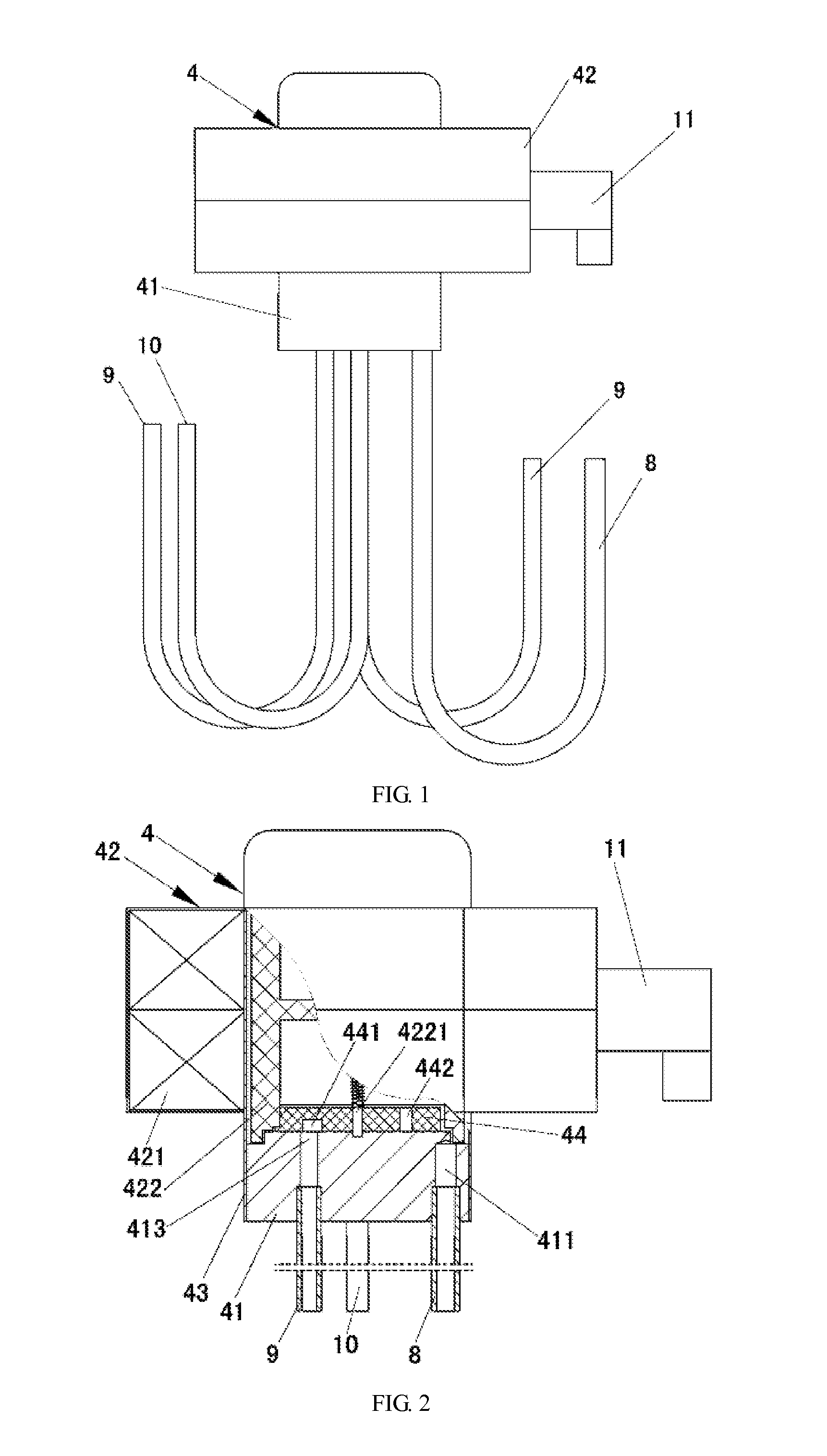
[0056]Referring to FIG. 1-FIG. 35, an electric valve includes a valve seat 41, an electric motor 42 and a valve cap 43; an inlet 411, a pressure relief port 412 and a plurality of outlets 413 are set on the valve seat 41, wherein the pressure relief port 412 and the outlets 413 are located on the upper surface of the valve seat 41; the valve cap 43 is covered above the valve seat 41; the electric motor 42 is fixedly set on the valve cap 43, and the electric motor 42 includes a stator 421 and a rotor 422, wherein the stator 421 is set on the outer surface of the valve cap 43, and the rotor 422 is set in the intracavity of the valve cap 43; the central part of the rotor 422 is provided with a mandrel 4221, and the rotor 422 may rotate around the axis of the mandrel 4221; the lower end of the mandrel 4221 is fixedly provided with a valve core 44 that is opened with a pressure-relief diversion slot 441 and a through slot 442, and the lower surface of the valve core 44 contacts the upper...


PUM


Abstract

The present invention discloses an electric valve and a refrigerating system comprising the same, wherein an inlet (411), a pressure relief port (412) and a plurality of outlets (413) are set on a valve seat (41) of the electric valve; a valve cap (43) is covered above the valve seat (41); an electric motor (42) is fixedly set on the valve cap (43), a stator (421) of the electric motor (42) is set on the outer surface of the valve cap (43), and a rotor (422) is set in the intracavity of the valve cap (43); the lower end of a mandrel (4221) is fixedly provided with a valve core (44) that is opened with a pressure-relief diversion slot (441) and a through slot (442), wherein the pressure-relief diversion slot (441) is opened on the lower surface of the valve core (44), and the through slot (442) penetrates through the valve core (44) along the thickness direction of the valve core (44). A single-cycle refrigerating system, a dual-cycle refrigerating system and a triple-cycle refrigerating system all comprise such an electric valve, and the functions of the refrigerating system, for example, refrigerant bifurcation, cutoff and pressure relief, etc., may be realized by rotating the valve core (44) of the electric valve to different positions.

Description

FIELD OF THE INVENTION[0001]The present invention relates to an electric valve and a refrigerating system comprising the same.BACKGROUND OF THE INVENTION[0002]Most of the ordinary domestic refrigerators belong to vapour compression-type refrigerating systems, which realize a control on the temperature in the refrigerators by controlling the on and off of a compressor. However, when the compressor stops working, the pressures in the condenser and the evaporator tend to be balanced, and during the balancing process, the hot-state refrigerant flows into the evaporator via capillary tubes, which causes a part of meaningless energy dissipation to the refrigerator. When the compressor is started, a part of energy will be lost during the process that the condenser and the evaporator reestablish a pressure difference, and the more frequently the refrigerator is turned on and turned off, the more energy will be dissipated. This part of energy dissipation caused by the on and off of the compr...

Claims


Application Information

Patent Timeline
IPC IPC(8): F25B41/04F25B41/06F25B5/02F16K11/074F16K31/04
CPCF25B41/04F16K11/074F25B41/067F25B5/02F16K31/041F25B2600/2507F16K11/0743F25B5/00Y10T137/86622Y10T137/86638F25B41/385F25B41/20F25B41/37
Inventor JING, SONGWEI, BANGFUHUANG, YONGSHOUJIA, SHOUTAOLI, QINGSONG
Owner CHANGHONG MEILING CO LTD
Learn More