
Transmission Having a Continuously or Infinitely Variable Variator Drive

a technology of variator drive and continuously or infinitely variable transmission, which is applied in the direction of mechanical equipment, transportation and packaging, etc., can solve the problems of limited ratio range of continuously variable transmission known in the art, and the limitation of transmitting small amounts of power, so as to increase the power improve the torque capacity of the variator, and expand the ratio range

Inactive Publication Date: 2015-08-13
DANA CORP
View PDF1 Cites 28 Cited by
  • Summary
  • Abstract
  • Description
  • Claims
  • Application Information

AI Technical Summary

Benefits of technology

The patent describes a variable transmission for commercial vehicles that expands the ratio range and increases power capacity. It includes three clutches and three brakes that allow the transmission to function as an infinite and a continuous variable transmission. Additionally, a bevel gear differential is included to improve torque capacity and efficiency. The bevel gears apply torque to the first drive member and the output shaft when the input shaft is rotated. The differential is rotatably supported within the housing. The technical effects of the patent text are to expand the range of ratios and increase power capacity of the vehicle's transmission, while also improving efficiency and reducing torque applied to the carrier assembly.

Problems solved by technology

Continuously variable transmissions known in the art tend to have limited ratio ranges and are typically limited to transmitting smaller amounts of power.

Method used


Image

  • Transmission Having a Continuously or Infinitely Variable Variator Drive
  • Transmission Having a Continuously or Infinitely Variable Variator Drive
  • Transmission Having a Continuously or Infinitely Variable Variator Drive

Examples


Embodiment Construction

[0041]Provided herein is a transmission having a variator drive capable of being placed in a continuously variable operating mode or an infinitely variable operating mode, capable of having a wide ratio range, and capable of transmitting larger amounts of power. Additional variable transmission details are described in US non-prov number of U.S. application Ser. No. 13 / 743,951 filed Jan. 17, 2013, and / or PCT / US2013 / 026037 filed Feb. 14, 2013, incorporated herein by reference in their entirety.

[0042]In a vehicle, a variable transmission 2 may be used to replace a conventional transmission in a vehicle driveline. The variable transmission 2 is located between an engine 4 and a vehicle output 6 as shown in FIG. 1. The vehicle output 6 may be a drive shaft or a differential, for example. A torsional dampener 16 is also typically disposed between the engine 4 and the variable transmission 2 to reduce vibration and torque peaks.

[0043]Provided herein is a variable transmission comprising t...


PUM


Abstract

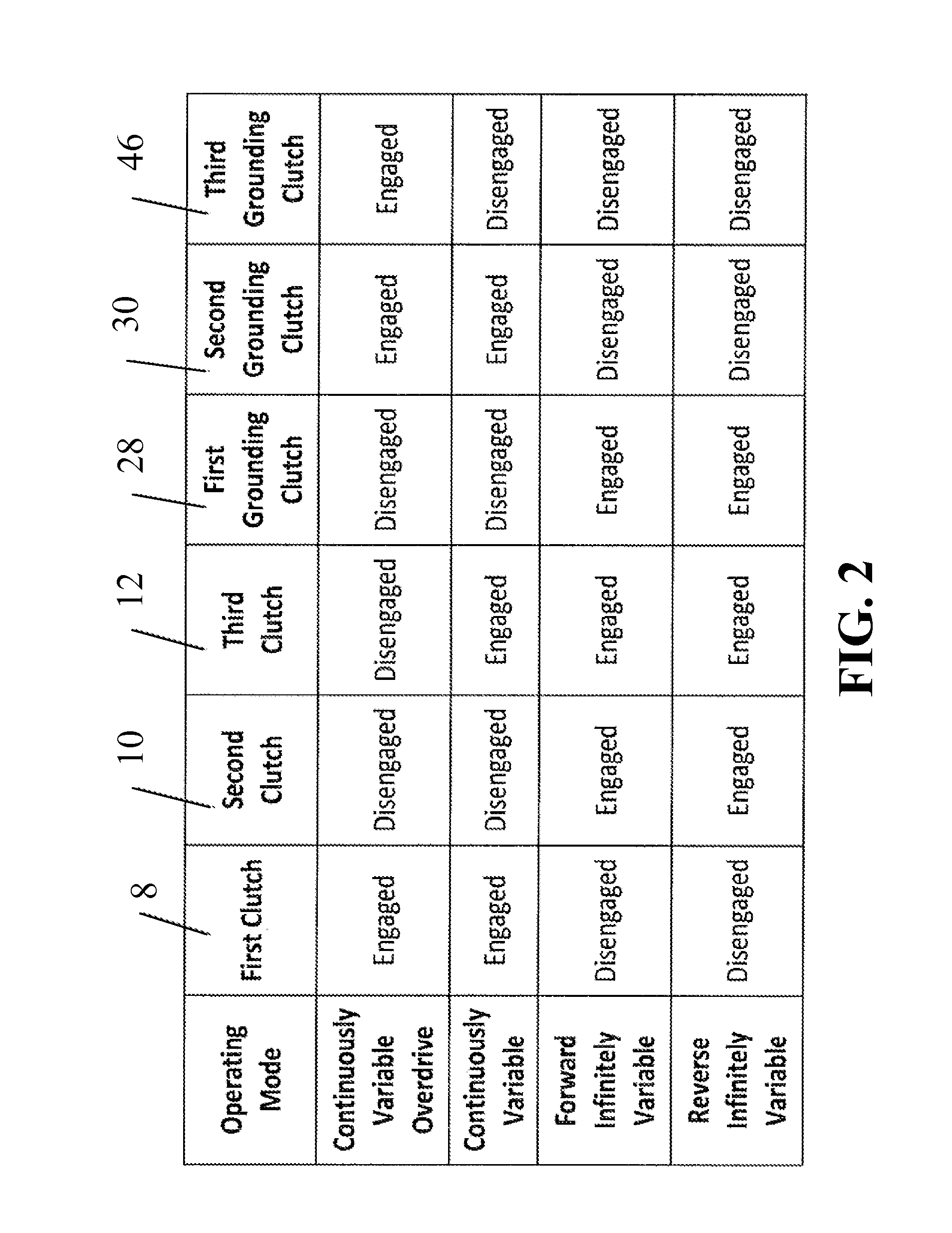
A transmission having a variator drive capable of being placed in a continuously variable operating mode or an infinitely variable operating mode, capable of having a wide ratio range, and capable of transmitting large amounts of power. Variable transmissions comprising three clutches, three grounding clutches or brakes, and a variator comprising a plurality of tilting variators balls disposed between a first drive ring and a second drive ring allow a single variator to function as an infinitely variable transmission when power is inputted to the carrier assembly and as a continuously variable transmission when power is inputted through a first ring assembly. Certain embodiments include a differential that allows a parallel power path around the variator to improve the variator torque capacity and a direct drive mode to improve the efficiency of the variator.

Description

CROSS-REFERENCE[0001]This application claims the benefit of U.S. Provisional Application No. 61 / 697,378, filed Sep. 6, 2012 and U.S. Provisional Application No. 61 / 780,634, filed Mar. 13, 2013, which are incorporated herein by reference in their entirety.BACKGROUND OF THE INVENTION[0002]A vehicle having a driveline including a continuously variable transmission allows an operator of the vehicle or a control system of the vehicle to vary a drive ratio in a stepless manner, permitting a power source of the vehicle to operate at its most efficient rotational speed. Further, the continuously variable transmission may be configured to be an infinitely variable transmission, wherein the vehicle can be steplessly shifted from a forward mode to a neutral mode or even to a reverse mode. Continuously variable transmissions known in the art tend to have limited ratio ranges and are typically limited to transmitting smaller amounts of power.SUMMARY OF THE INVENTION[0003]Provided herein is a var...

Claims


Application Information

Patent Timeline
IPC IPC(8): F16H37/02F16H15/52
CPCF16H37/022F16H15/52F16H2200/2046F16H2200/2005F16H2037/026F16H37/02
Inventor ZIECH, JAMES F.COOPER, KENNETH E.
Owner DANA CORP
Learn More