Optical Inspection Apparatus and Optical Sorting Apparatus

Inactive Publication Date: 2015-08-06
KII TEKU INC
View PDF4 Cites 2 Cited by
  • Summary
  • Abstract
  • Description
  • Claims
  • Application Information

AI Technical Summary

Benefits of technology

The invention is a way to tell the difference between optical information from inspected products and background optical information using a simple and cost-effective arrangement of an optical system. This helps to improve the accuracy and efficiency of analyzing and sorting products using optical information. The invention uses a hyper- or multispectral camera to detect the background signal in a simple way.

Problems solved by technology

If the products to be treated are characterized by a high number of optical properties, practical design of such a background element is a problem.

Method used


Image

  • Optical Inspection Apparatus and Optical Sorting Apparatus
  • Optical Inspection Apparatus and Optical Sorting Apparatus
  • Optical Inspection Apparatus and Optical Sorting Apparatus

Examples


Embodiment Construction

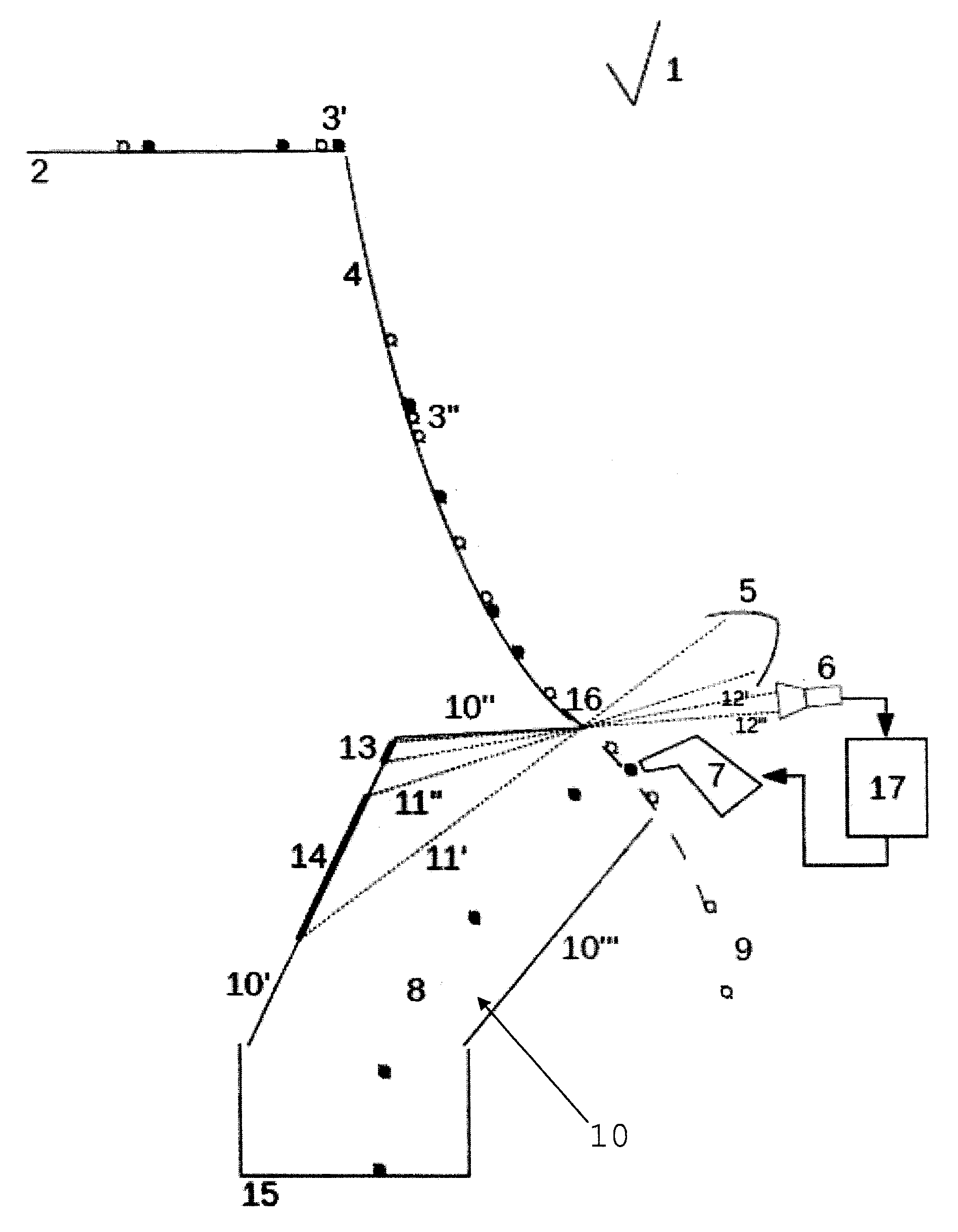
[0037]The present invention will be described by means of some examples referring to certain figures without any limiting character. The figures are only schematic and non-limiting. Dimensions of certain elements can be exaggerated or not to scale in the figures. However, this is for illustrative reasons. The dimensions and relative dimensions therefore do not necessarily correspond to reality.

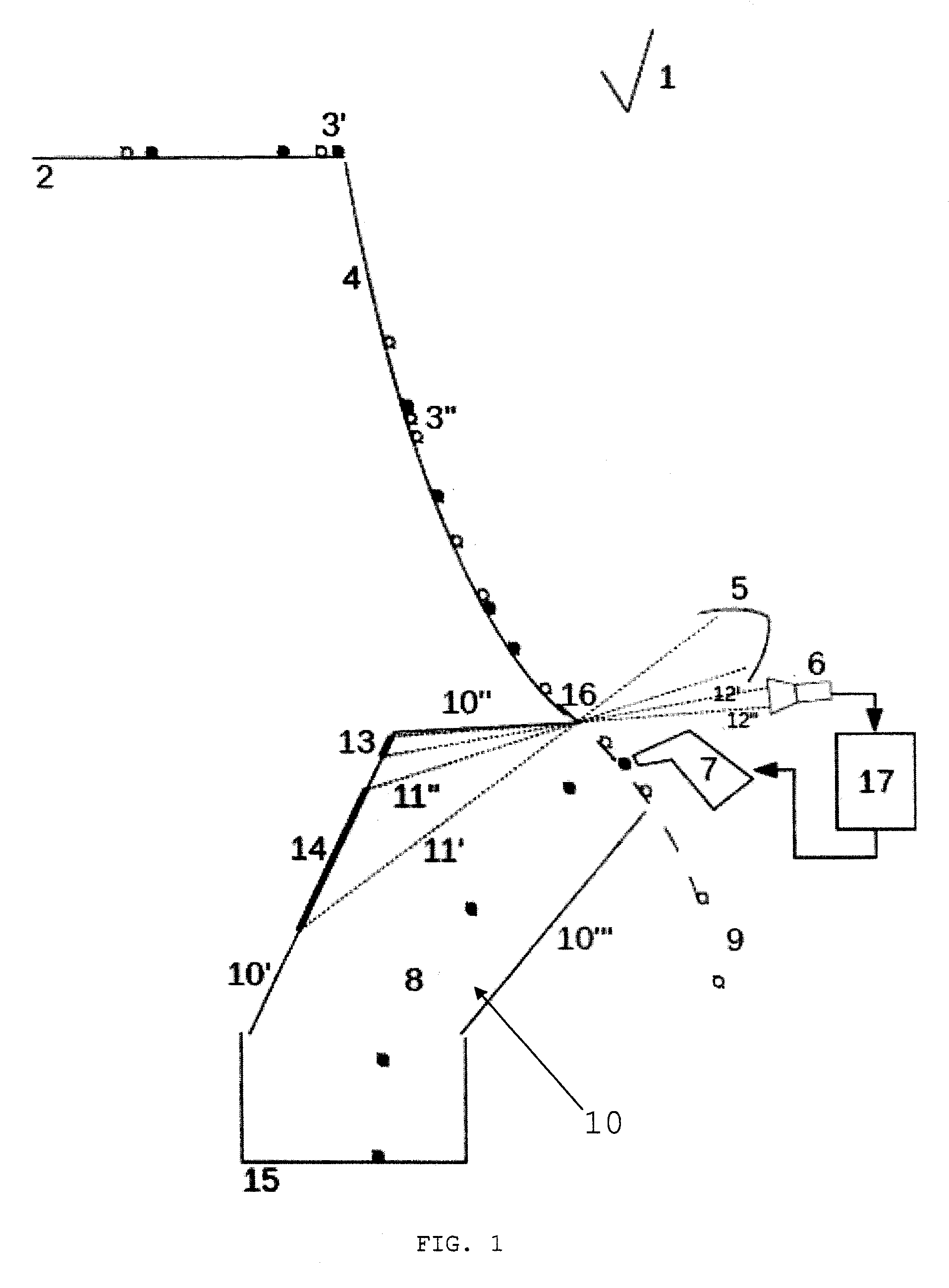
[0038]FIG. 1 shows a possible embodiment of an apparatus according to the invention for sorting of a continuous stream of products 3′, 3″. This is an example of a so-called ‘free-fall’ apparatus. The apparatus comprises the following components: a transport mechanism, which includes a conveyor belt or vibrating plate 2 and a chute 3. The conveyor belt or vibrating plate 2 transports a continuous stream consisting of a single layer of products 3′, 3″ to the guide plate 4 which supports said product stream 3′, 3″ during its fall so that, on leaving the guide plate, the product stream 3′, 3″ foll...


PUM


Abstract

The invention concerns an apparatus for inspection of products (3′, 3″), provided with a transport mechanism (2) configured to transport a continuous stream of products (3′, 3″) so that, on leaving the transport mechanism, the product stream (3′, 3″) follows a free-fall path along which it is fed in a single product layer through an inspection zone (16), which has a length (L) that at least corresponds to the width of the aforementioned single product layer, a light source (5, 5′) configured to illuminate said inspection zone (16), a detection unit (6), configured to optically scan the illuminated inspection zone (16), an analysis unit (17) and possibly a removal unit (7) and also a background element (10′), which is situated behind the falling product stream, seen from the position of the detection unit, positioned so that:—light beams from the light source impinge on an illumination zone (14) of the background element when these beams do not impinge on a product from the product stream (3′, 3″),—the detection unit can only receive an image of a detection zone (13) of the background element, characterized in that the background element is mounted so that the illumination zone (14) and the detection zone (13) are separated from each other.

Description

TECHNICAL FIELD[0001]This application concerns machines for continuous inspection as well as machines for continuous sorting of a stream of products, such as bulk products, which are transported past an inspection unit in a single layer, these products preferably being inspected for their optical properties.[0002]The application especially concerns a setup of the optical system in order to solve the problem of background detection in a simple and cost-effective manner.PRIOR ART[0003]Machines for inspection and sorting of bulk products supplied in a continuous stream are known. Such inspection machines comprise a feed unit, an optical system and an analysis unit. A sorting machine also has a removal unit and a discharge unit.[0004]The feed unit supplies a stream of products which are to be inspected continuously through an inspection zone that is scanned by the optical system, which is in operational communication with the analysis unit. The analysis unit analyzes each separate produ...

Claims


Application Information

Patent Timeline
IPC IPC(8): G01N21/89
CPCB07C5/3425G01N2021/8908G01N2021/845B07C2501/0018G01N21/8901B07C5/363
Inventor DIRIX, BERT
Owner KII TEKU INC
Why Eureka
Try Eureka