Cutter assembly having dual locking effect

a cutter and locking technology, applied in the field of cutter assemblies, can solve the problems that the cutter having the conventional automatic locking device, which can only be applied to cutting a thin object, such as paper, and cannot be applied to cutting a thick object. to achieve the effect of enhancing the convenience of using the cutter assembly

Active Publication Date: 2015-07-30
SDI CORPORATION
View PDF17 Cites 8 Cited by
  • Summary
  • Abstract
  • Description
  • Claims
  • Application Information

AI Technical Summary

Benefits of technology

The invention is a cutter assembly with two locking devices that allows for both automatic and screw-based locking. This improves the ease of use by allowing users to choose the best locking method for their specific needs. This design provides both convenience and versatility for using the cutter assembly.

Problems solved by technology

However, although the conventional automatic locking device is convenient in use, the engaging force between the engaging block and the engaging teeth in the blade holder is not sufficient.
Therefore, a cutter having the conventional automatic locking device can only be applied to cut a thin object, such as paper, and cannot be applied to cut a thick object.
Thus, the conventional screw locking device is not convenient in use.

Method used


Image

  • Cutter assembly having dual locking effect
  • Cutter assembly having dual locking effect
  • Cutter assembly having dual locking effect

Examples


Embodiment Construction

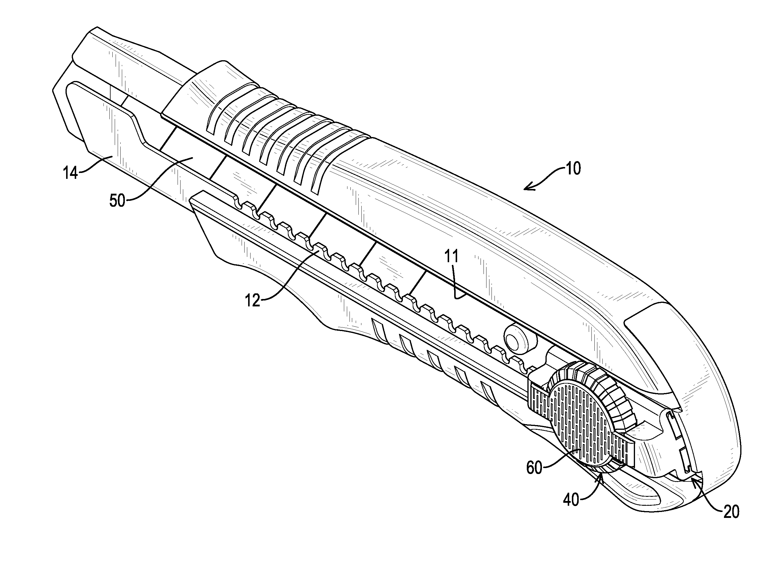
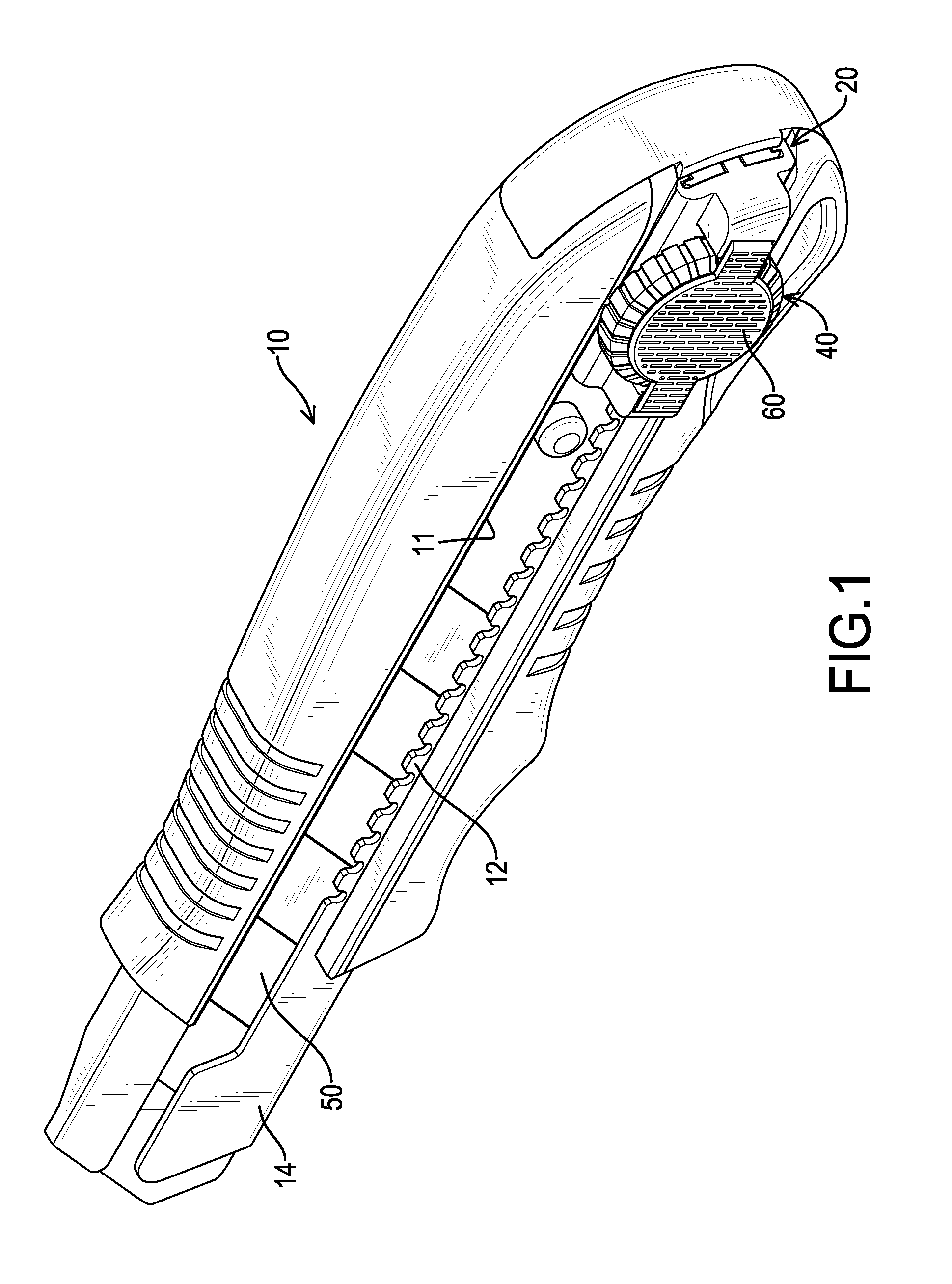
[0027]With reference to FIGS. 1 to 4, a cutter assembly in accordance with the present invention comprises a blade holder 10, a slider 20, an automatic locking device 30, a screw locking device 40 and a blade 50.

[0028]The blade holder 10 comprises a guiding channel 11 and a metal base 14. The guiding channel 11 is defined in the blade holder 10 and has two inner edges. The metal base 14 has multiple engaging teeth 12 formed on the metal base 14 at a side facing the guiding channel 11 and arranged in a line along at least one of the inner edges of the guiding channel 11.

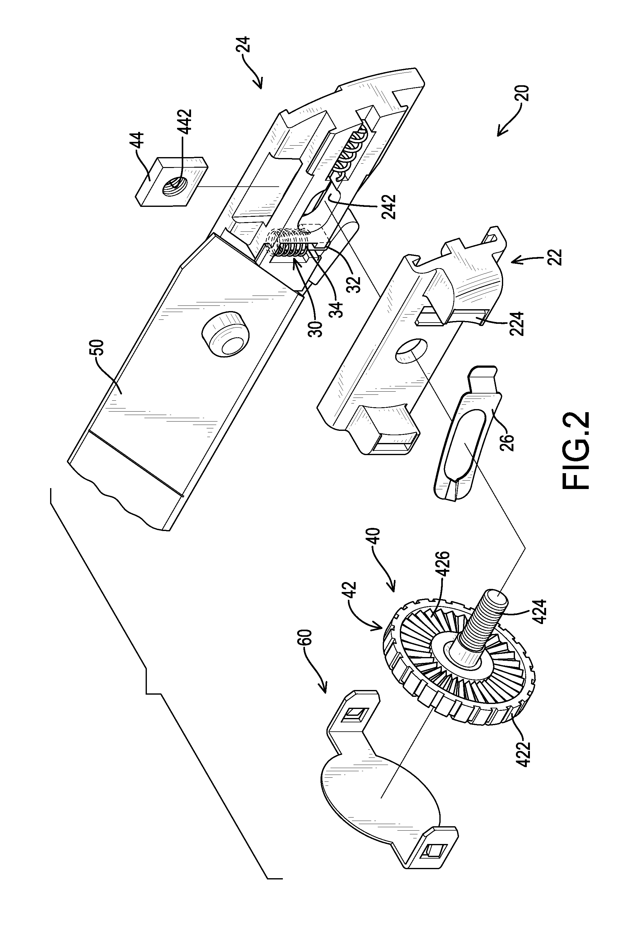
[0029]The slider 20 is mounted slidably on the blade holder 10 relative to the guiding channel 11 and comprises an upper sliding member 22 and a lower sliding member24.

[0030]The automatic locking device 30 is mounted on the slider 20 and has a resilient member selectively engaging at least one of the engaging teeth 12. In the first embodiment, the resilient member comprises an engaging block 32 and a spring 34. The en...


PUM


Abstract

A cutter assembly has a blade holder, a slider, an automatic locking device, a screw locking device and a blade. The blade holder has a guiding channel defined in the blade holder and having two inner edges. Multiple engaging teeth are arranged in a line along at least one of the inner edges. The slider is mounted slidably on the blade holder relative to the guiding channel. The automatic locking device is mounted on the slider and has a resilient member selectively engaging at least one of the engaging teeth. The screw locking device is mounted on the slider and has a relative travel distance between the screw locking device and the slider. The blade is mounted slidably in the blade holder and connected to the slider.

Description

BACKGROUND OF THE INVENTION[0001]1. Field of the Invention[0002]The present invention relates to a cutter assembly, and more particularly to a cutter assembly having two locking devices.[0003]2. Description of Related Art[0004]A retractable cutter substantially comprises a blade holder, a blade and a slider. The slider is mounted on the blade holder. The blade is mounted slidably in the blade holder and is connected to the slider. When the slider is pushed, the blade is moved relative to the blade holder to extend out of the blade holder to enable a user to cut an object by the cutter. For use of holding the blade at a desired position with a desired extension length relative to the blade holder, a locking device is mounted on the slider. The conventional locking devices include two different types, an automatic locking device and a screw locking device. The conventional automatic locking device substantially comprises an engaging block and a spring. Multiple engaging teeth are form...

Claims


Application Information

Patent Timeline
IPC IPC(8): B26B5/00B26B1/04B26B1/08
CPCB26B5/001B26B1/048B26B1/08B26B5/002
Inventor WU, CHIEN-LUNGHSU, CHIH-WEICHU, YAO-CHIAPAI, CHENG-YUHUNG, CHI-CHENG
Owner SDI CORPORATION
Why Eureka
Try Eureka