
Head-mounted display device and optical unit

Inactive Publication Date: 2015-07-16
SONY CORP
View PDF13 Cites 145 Cited by
  • Summary
  • Abstract
  • Description
  • Claims
  • Application Information

AI Technical Summary

Benefits of technology

The present technology provides a head-mounted display apparatus and optical unit with a display panel and ocular lens for projecting video images into a user's eyes. The display panel can be accurately aligned with the ocular lens based on the optical properties of the lens, and the alignment is precise enough to match the pixel size of the display panel or less without compromising the device's compactness and light weight.

Problems solved by technology

If, in a head mount display, right and left optical axes of an optical system are not coincident with each other with high precision, then an observing user ends up feeling uncomfortable with the video.
However, it is difficult to meet the aforementioned required precision with mechanical positioning such as, for example, abutting and hole-mating.
Furthermore, in order to realize a structure that meets the aforementioned required precision with the mechanical positioning, higher precision of components and management according to the precision are required, causing increased costs of components and increased assembly costs.
However, if the substrate of the liquid crystal display panel main body and the ocular lens are made integral, then the positioning precision of the liquid crystal display panel main body and the optical axis of the ocular lens is fixed at the time of molding, making it impossible to further perform positional adjustment with high precision.
Furthermore, it is considered that, when an ocular optical system is composed of a plurality of lenses, it is difficult to integrally mold a plurality of ocular lenses with a liquid crystal display panel main body being included.

Method used


Image

  • Head-mounted display device and optical unit
  • Head-mounted display device and optical unit
  • Head-mounted display device and optical unit

Examples


Embodiment Construction

[0048]Hereinafter, embodiments of the technology disclosed in the present specification will be described in detail with reference to the drawings.

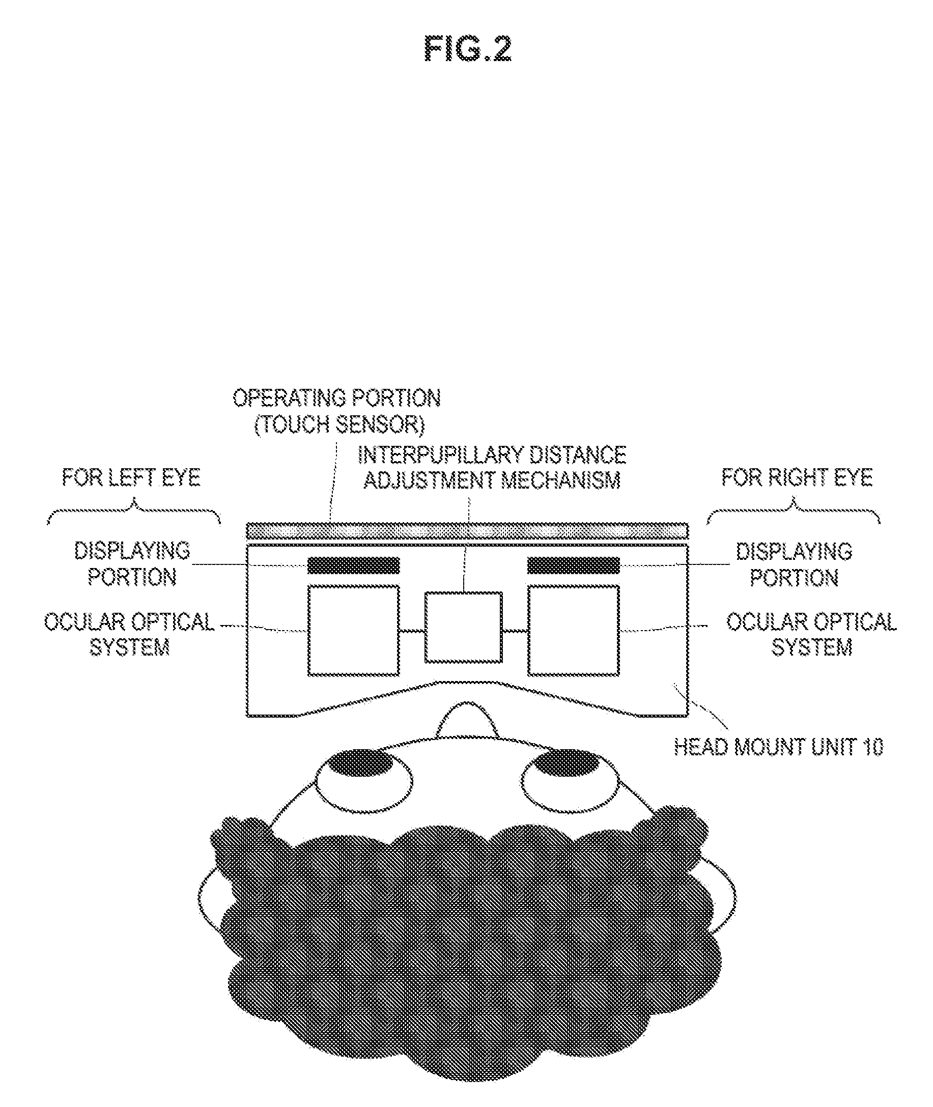
[0049]FIG. 1 schematically illustrates the configuration of an image display system including a head mount display. The illustrated system is composed of a Blu-ray disc reproducing apparatus 20 which is a source of viewing contents, a front end box 40 for processing an AV signal output from the Blu-ray disc reproducing apparatus 20, a head-mounted display apparatus (head mount unit) 10 which is an output destination of the reproduced contents of the Blu-ray disc reproducing apparatus 20, and a high-vision display (e.g., HDMI (registered trademark) compatible television) 30 which is another output destination of the reproduced contents of the Blu-ray disc reproducing apparatus 20. The head mount unit 10 and the front end box 40 constitute one set of a head mount display.

[0050]The front end box 40 corresponds to an HDMI (registered trademar...


PUM


Abstract

Provided is a head-mounted display apparatus including a display panel portion including a display panel configured to display an image, an ocular optical portion having a lens integrally formed with an attaching part to which the display panel portion is attached, and configured to perform optical processing for a video displayed by the display panel, a video signal processing portion configured to process a video signal, and a display controlling portion configured to drive the display panel based on the video signal processed at the video signal processing portion.

Description

TECHNICAL FIELD[0001]The technology disclosed in the present specification relates to a head-mounted display apparatus and an optical unit to be used by mounting them on the head of a user, and in particular a head-mounted display apparatus and an optical unit having a display panel for displaying a video and an ocular optical portion for projecting the image displayed on the display panel into user's eyes.BACKGROUND ART[0002]There is widely known a displaying apparatus mounted on a head to view a video, that is, a head mount display (HMD). The head mount display has an optical unit for each of right and left eyes and is configured to be able to control the senses of sight and hearing when it is used with headphones. When it is configured so as to be completely cut off from the outside world at the time it is attached to the head, the virtual reality is increased at the time of looking and listening. Also, the head mount display can reflect different videos to right and left eyes, a...

Claims


Application Information

Patent Timeline
IPC IPC(8): G02B27/01
CPCG02B2027/0178G02B27/0172G02B27/017
Inventor HIRAI, SHINJI
Owner SONY CORP
Learn More