
Battery pack, method for detecting battery pack, charging assembly and electric tool

a battery pack and charging assembly technology, applied in the direction of batteries, instruments, safety/protection circuits, etc., can solve the problems of insufficient power, limiting the development of wireless electric tools, and undesirable endurance of driving large-power electric tools

Active Publication Date: 2015-07-02
CHERVON HK LTD WANCHAI
View PDF5 Cites 37 Cited by
  • Summary
  • Abstract
  • Description
  • Claims
  • Application Information

AI Technical Summary

Benefits of technology

The patent describes a battery pack with a plurality of battery cells connected in parallel through series connection units. The battery control module detects voltage signals from each unit and uses a disconnection detecting module to determine if there is a disconnection of the battery cells. This allows for the detection of battery cell failure and the replacement of malicious cells. The battery control module can also determine the voltage of the series connection unit based on the voltage signals and the time, and use this information to determine if disconnection has occurred. The patent also describes the use of a temperature module to detect battery cell failure. The technical effects of this patent include improved battery pack reliability and durability, as well as improved battery control and safety.

Problems solved by technology

A battery pack, as a power source of a wireless electric tool, limits the development of wireless electric tools.
Battery packs typically have an output voltage below 30V, and usually lead to problems such as insufficient power and undesirable endurance upon driving large-power electric tools.
Currently there is no charging assembly that has an output voltage above 30V and a circuit structure that can be safely used during charging.
Likewise, currently there is no corresponding charging control method for such a charging assembly.

Method used


Image

  • Battery pack, method for detecting battery pack, charging assembly and electric tool
  • Battery pack, method for detecting battery pack, charging assembly and electric tool
  • Battery pack, method for detecting battery pack, charging assembly and electric tool

Examples


Embodiment Construction

[0045]The following description of example methods and apparatus is not intended to limit the scope of the disclosure to the precise form or forms detailed herein. Instead the following description is intended to be illustrative so that others may follow its teachings.

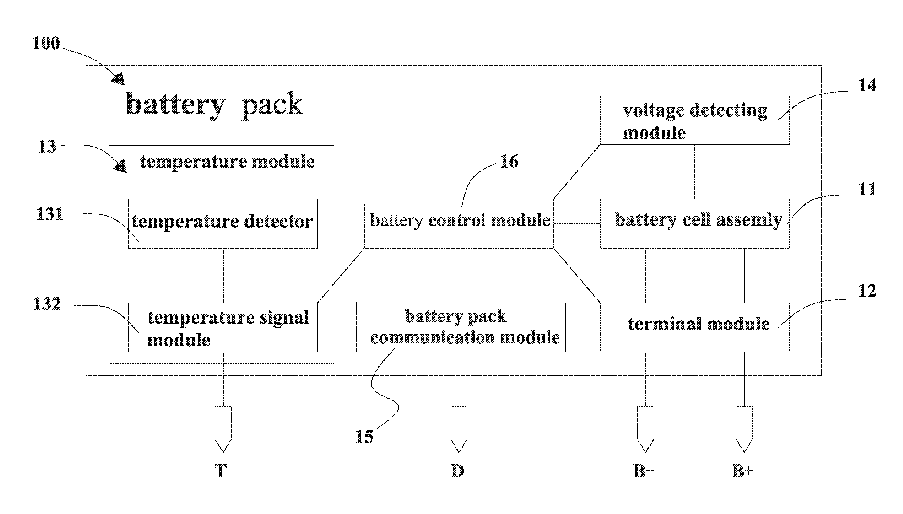
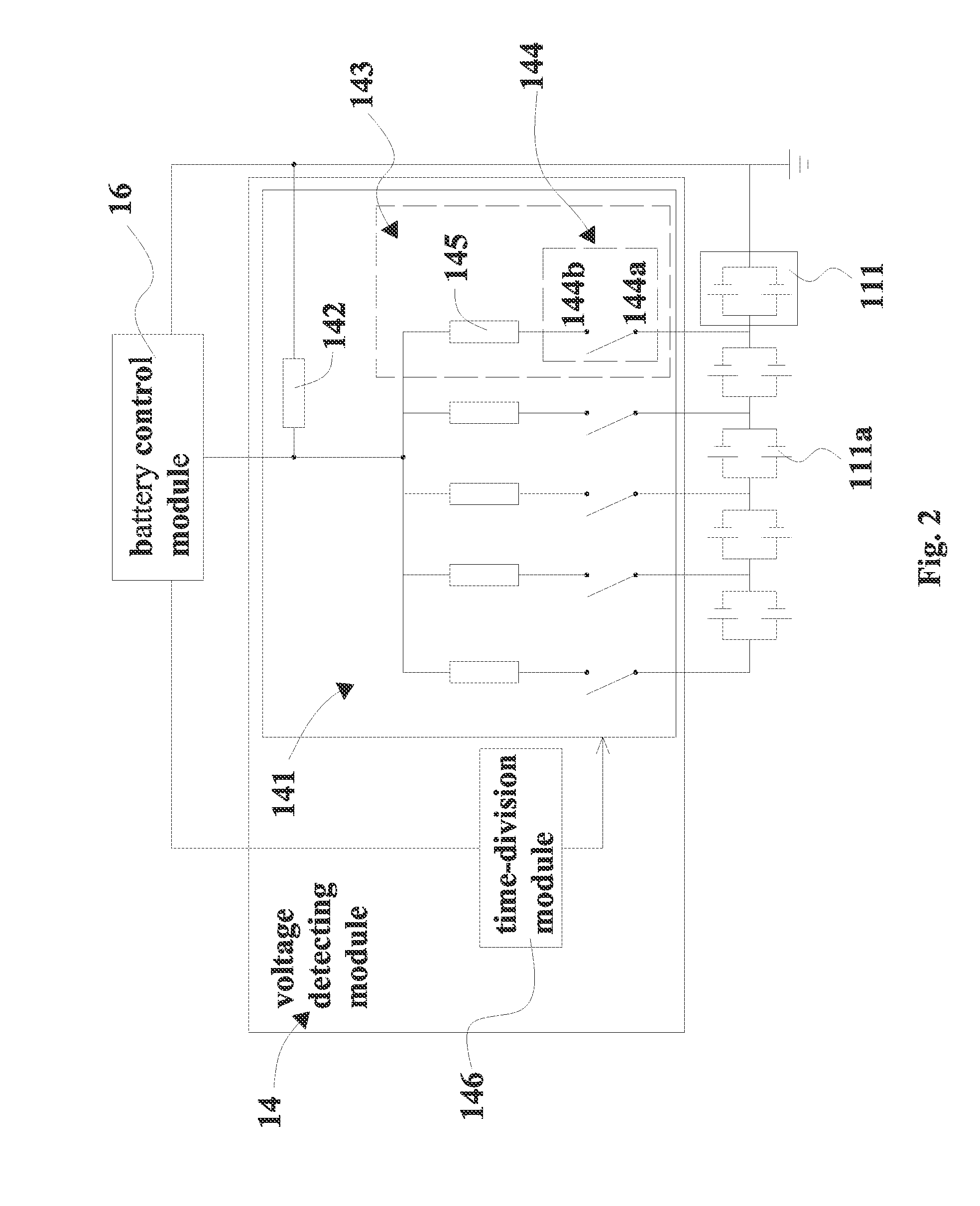
[0046]Referring to FIGS. 1-3, an example battery pack 100 in some instances comprises a battery cell assembly 11, a terminal module 12, a temperature module 13, a voltage detecting module 14, a battery pack communication module 15 and a battery control module 16 controlling them. The example battery cell assembly 11 may comprise a plurality of series connection units 111, and the series connection units 111 may be connected in series to form the battery cell assembly 11. The example series connection unit 111 comprises a plurality of battery cells 111a, and the battery cells 111a in the same series connection unit 111 may be connected in parallel.

[0047]As shown in FIG. 2 and FIG. 3, each example series connection unit ...


PUM

PropertyMeasurementUnit
output voltageaaaaaaaaaa
voltageaaaaaaaaaa
output voltageaaaaaaaaaa

Abstract

A battery pack, a method for detecting the battery pack, a charging assembly, and an electric tool are provided for detecting voltage and disconnection of the battery cells. The battery pack may have an output voltage of at least 56V and may include a plurality of series connection units. A voltage detecting module may be utilized for detecting voltage in the battery pack. A battery control module configured to control voltage detecting module may also be employed. The method may involve determining whether the series connection units are disconnected based on rates of voltage change or internal-resistance of the series connection units.

Description

CROSS REFERENCE TO RELATED APPLICATION[0001]This application is a non-provisional application claiming priority from Chinese Patent Application No. CN201310752233.2, filed Dec. 31, 2013; Chinese Patent Application No. CN201410521089.6, filed Sep. 30, 2014; Chinese Patent Application No. CN201410523174.6, filed Sep. 30, 2014; and Chinese Patent Application No. 201410521086.2, filed Sep. 9, 2014, all of which are incorporated herein by reference in their entireties.FIELD OF THE DISCLOSURE[0002]The present disclosure relates to a battery pack, a method for detecting the battery pack, a charging assembly, and an electric tool.BACKGROUND[0003]A battery pack, as a power source of a wireless electric tool, limits the development of wireless electric tools. Battery packs typically have an output voltage below 30V, and usually lead to problems such as insufficient power and undesirable endurance upon driving large-power electric tools. Currently there is no charging assembly that has an outp...

Claims


Application Information

Patent Timeline
Patent Type & Authority Applications(United States)
IPC IPC(8): G01R31/36H01M10/48H01M10/42H02J7/00
CPCG01R31/362H02J7/0013H01M2010/4271H01M10/425H01M2220/30H01M10/482G01R31/3835G01R31/382G01R31/396G01R31/3842Y02E60/10G01R31/54G01R31/389H02J7/0026H02J7/0029H02J7/007184G01R31/36G01R31/68
Inventor YANG, DEZHONGSHI, PINGBOLIU, LEIGENG, ZHENGWANG, LEIDUAN, JUNYAXIANG, YINGDIAN
Owner CHERVON HK LTD WANCHAI
Learn More