
Well intervention semisubmersible vessel

a semi-submersible, well-interpreted technology, applied in the field of well-interpreted semi-submersible vessels, can solve the problems of over-use of full-size drilling bop stacks and lmrps, design of well-interpreted semi-submersibles, and inability to design, etc., to achieve the effect of facilitating equipment movement, facilitating lifting, and improving the efficiency of subsea equipment and surface well service equipmen

Active Publication Date: 2015-07-02
HELIX ENERGY SOLUTIONS GROUP
View PDF4 Cites 8 Cited by
  • Summary
  • Abstract
  • Description
  • Claims
  • Application Information

AI Technical Summary

Benefits of technology

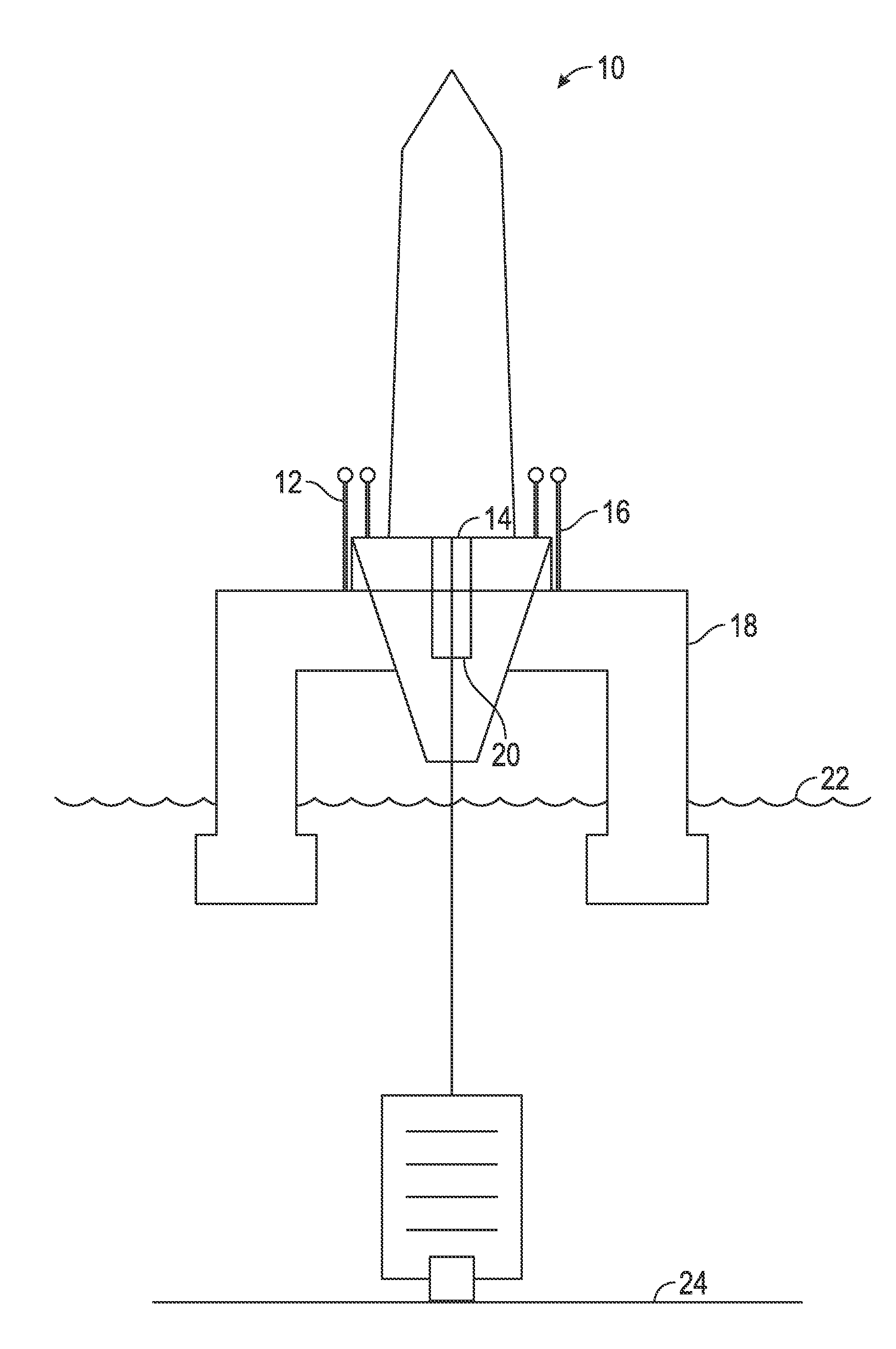
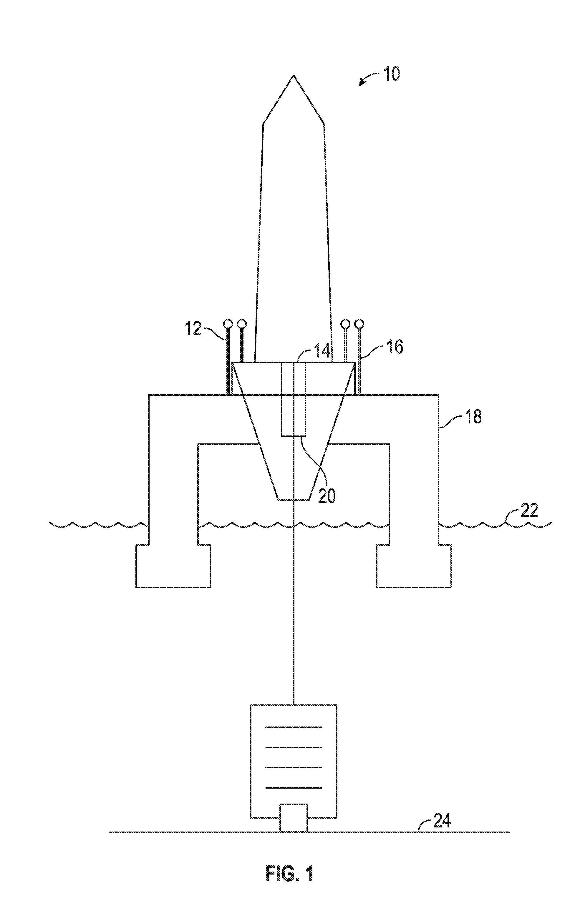
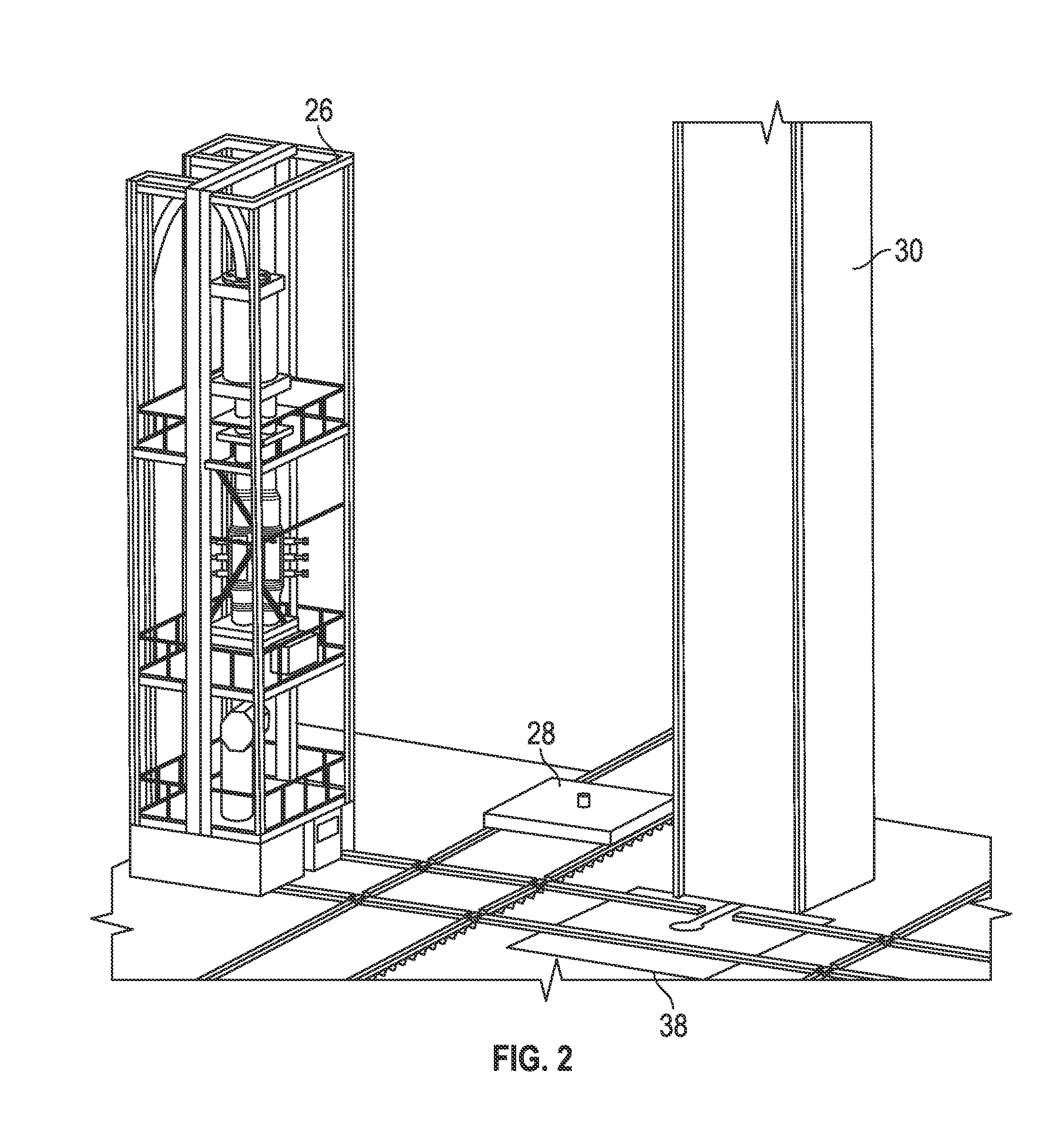
The patent describes a new design for a semi-submersible vessel that allows for more efficient operations in subsea well intervention work. The vessel has a flat, flush deck with no derrick substructure, which allows for better handling of equipment, quick rigging up and down, and ease of movement. The heavy lift crane capability also enables the vessel to handle large equipment. The combination of heavy lift and open deck design also eliminates the need for riser tensioners, which increases efficiency during well intervention operations. The vessel can also access well service equipment at height safely using a self-standing skidding lift frame. The design also allows for hanging off two strings of pipe within the moonpool, reducing the amount of round trip operations required for well intervention work.

Problems solved by technology

Accordingly, the equipment for assembling, handling, transporting, and positioning the massive BOP stack and the LMRP underneath the drill floor becomes the center issue in the drilling system design layout.
The design of a Well Intervention Semisubmersible, however, is not intended for drilling of a new well to the reservoir formation.
The use of a full size drilling BOP stack and LMRP is considered as overkill for well intervention.

Method used


Image

  • Well intervention semisubmersible vessel
  • Well intervention semisubmersible vessel
  • Well intervention semisubmersible vessel

Examples


Embodiment Construction

[0021]The drawings described above and the written description of specific structures and functions below are presented for illustrative purposes and not to limit the scope of what has been invented or the scope of the appended claims. Nor are the drawings drawn to any particular scale or fabrication standards, or intended to serve as blueprints, manufacturing parts list, or the like. Rather, the drawings and written description are provided to teach any person skilled in the art to make and use the inventions for which patent protection is sought. Those skilled in the art will appreciate that not all features of a commercial embodiment of the inventions are described or shown for the sake of clarity and understanding.

[0022]Persons of skill in this art will also appreciate that the development of an actual, real-world commercial embodiment incorporating aspects of the inventions will require numerous implementation specific decisions to achieve the developer's ultimate goal for the ...


PUM


Abstract

A well intervention semisubmersible vessel and method including a drilling rig further including a non-elevated derrick floor and a handling tower having a single point land out without riser tensioners. The vessel may also include a flush drill floor, a flush moonpool door, a lift frame and personnel access walkway wherein the lift frame is capable of being skidded into position by a skidding system capable of providing personnel access and wherein the skidding system comprises a plurality of skidding rails, at least one remotely operated vehicle, an intervention rising system and storage area, a crane, a moonpool and handling area, a moonpool trolley, at least one fluid pump, and / or at least one tank.

Description

CROSS REFERENCE TO RELATED APPLICATIONS[0001]This nonprovisional application for patent claims priority to, and hereby incorporates by reference, U.S. Provisional Application Ser. No. 61 / 922,441, entitled “Well Intervention Semisubmersible Vessel,” filed Dec. 31, 2013.BACKGROUND OF THE INVENTION[0002]1. Technical Field of Invention[0003]The invention disclosed and taught herein relates generally to a system and method for use in floating offshore environments including drilling rigs. The embodiments described below related generally to the design layout of equipment on an offshore Well Intervention Semisubmersible (WIS) platform specifically for the transport, deployment, and retrieval of well intervention subsea equipment.[0004]2. Background of the Invention[0005]A typical layout of an exploratory drilling rig is to place a pyramid type drilling derrick at or near the center of the upper deck with an “elevated drill floor.” These type of derricks are usually built of truss structur...

Claims


Application Information

Patent Timeline
Patent Type & Authority Applications(United States)
IPC IPC(8): B63B35/44B63B1/10E21B15/02
CPCB63B35/4413E21B15/02B63G2008/005B63B2003/147B63B1/107E21B15/003
Inventor CHIU, HINJOHNSTON, COLIN
Owner HELIX ENERGY SOLUTIONS GROUP
Learn More