Cover glass for photoelectric conversion device

a technology of photoelectric conversion device and cover glass, which is applied in the direction of sustainable buildings, transportation and packaging, instruments, etc., can solve the problems of annoyance of neighboring houses and significant deterioration of appearance, and achieve the effect of high transmittance gain

Active Publication Date: 2015-06-25
NIPPON SHEET GLASS CO LTD
View PDF1 Cites 14 Cited by
  • Summary
  • Abstract
  • Description
  • Claims
  • Application Information

AI Technical Summary

Benefits of technology

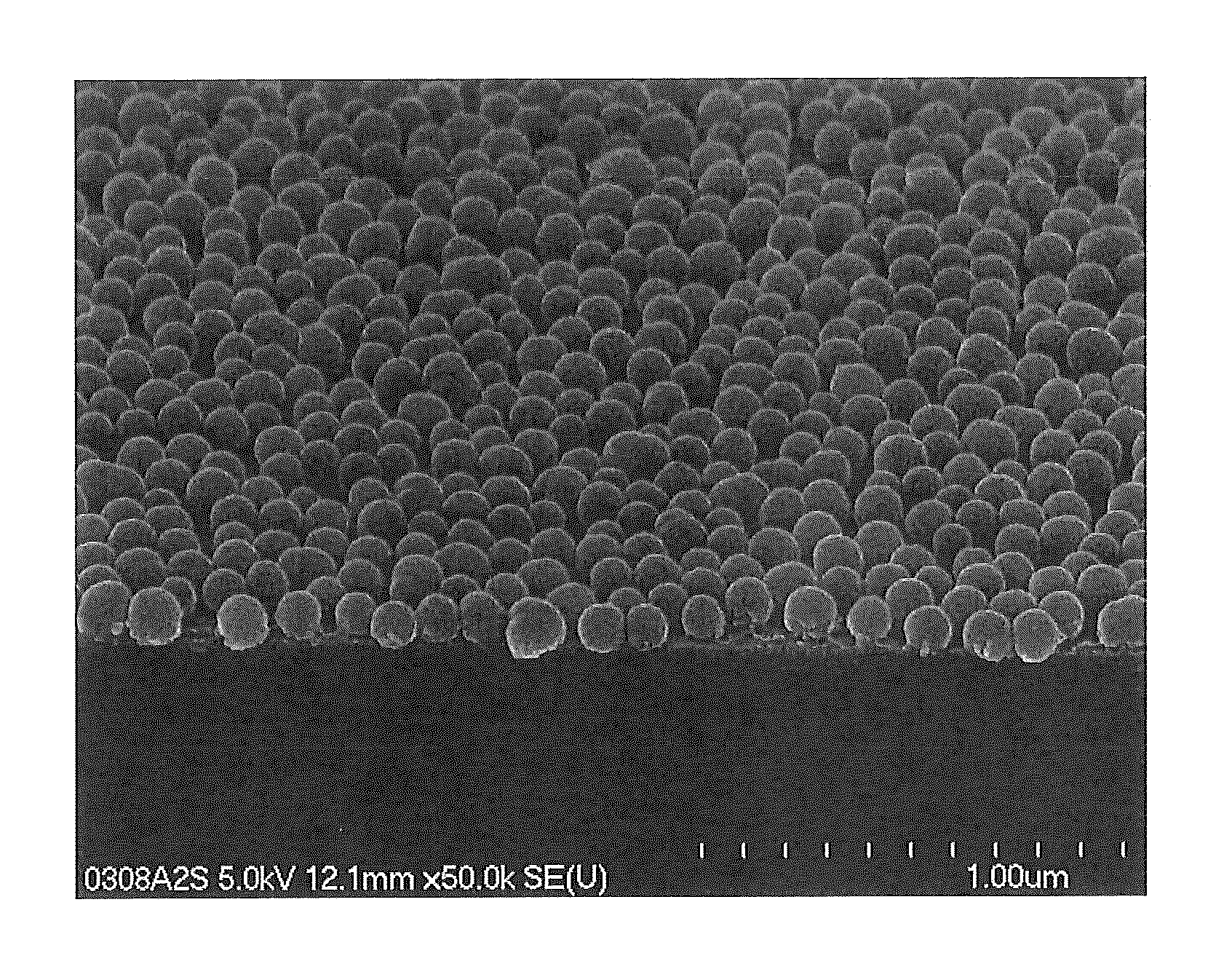
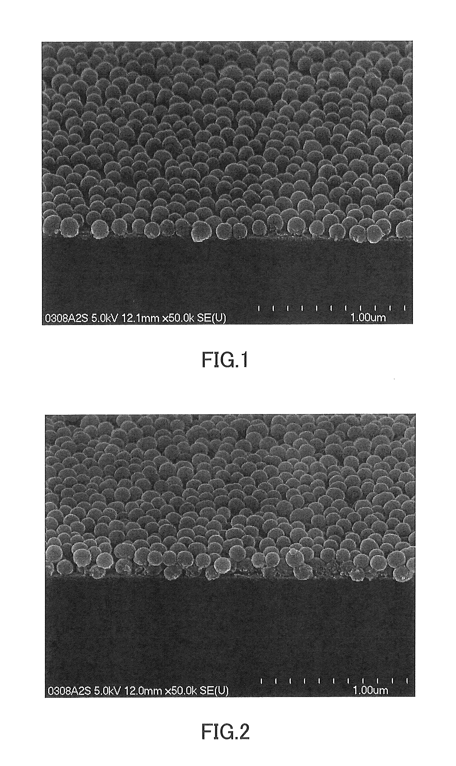
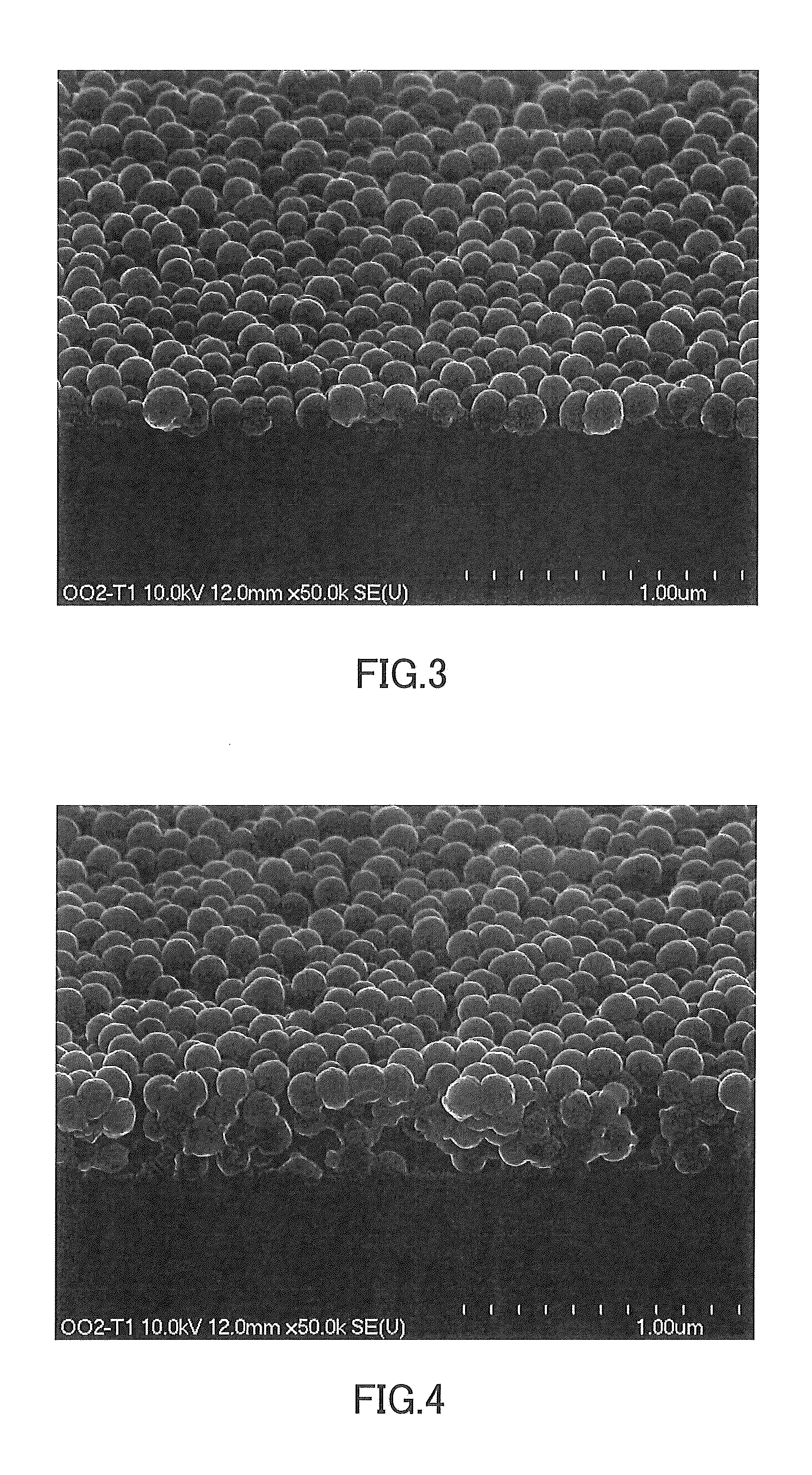
[0020]In the cover glass of the present invention, the average particle diameter of the fine silica particles contained in the reflection-reducing film is 50 to 200 nm, and the fine silica particles are uniformly arranged on the peak portions of the surface asperities in such a manner that the filling fraction F is 35 to 65%. Thus, the fine silica particles are arranged on the peak portions of the surface asperities at an appropriate density; consequently, the cover glass of the present invention exhibits a high transmittance gain.

Problems solved by technology

However, when the photoelectric conversion device is installed on the roof of a house, reflected light from the cover glass may cause annoyance to neighboring houses.
With a reflection-reducing film formed on that surface of a cover glass which has surface asperities, the appearance may be significantly deteriorated due to uneven reflection.

Method used


Image

  • Cover glass for photoelectric conversion device
  • Cover glass for photoelectric conversion device
  • Cover glass for photoelectric conversion device

Examples


example 1

Preparation of Coating Liquid

[0072]An amount of 39.1 parts by weight of a fine silica particle dispersion liquid (PL-7, manufactured by FUSO CHEMICAL CO., LTD., average particle diameter=100 nm, solid content concentration=23 weight %), 56.4 parts by weight of ethyl cellosolve, and 1 part by weight of 1N hydrochloric acid (hydrolysis catalyst) were stirred and mixed. Under further stirring, 3.5 parts by weight of tetraethoxysilane was added to the mixture, which was then stirred for further 8 hours with its temperature maintained at 40° C. Thus, a raw material liquid was obtained. In this raw material liquid, the solid content concentration was 9 weight %, and the ratio by weight of the fine particles to the binder (in terms of oxide content) in the solid contents was 90:10. It should be noted that the fine silica particles were solid (i.e., non-hollow) fine particles.

[0073]A coating liquid was obtained by stirring and mixing 11 parts by weight of the raw material liquid, 10.0 parts...

example 2 to example 8

[0077]Cover glasses according to Comparative Examples 2 to 8 were obtained in the same manner as in Example 1, except that the proportions of the materials for preparing the raw material liquid and the coating liquid, and the conditions for forming the reflection-reducing film (conditions for drying and conditions for calcining), were as shown in Table 2. In Example 3 and Example 4, as shown in Table 2, “CoatOSil 3505” manufactured by Momentive Performance Materials Japan LLC was used as the silicon-based surfactant. The thus-obtained cover glasses according to Examples 2 to 8 were evaluated for the above-described properties. The results of the evaluation are shown in Table 1.


PUM

PropertyMeasurementUnit
arithmetic average roughness Raaaaaaaaaaa

Abstract

A cover glass of the present invention for photoelectric conversion devices includes a glass sheet having surface asperities and a reflection-reducing film formed over the surface asperities of the glass sheet. The surface asperities of the glass sheet have an average spacing Sm of 0.3 mm or more and 2.5 mm or less and an arithmetic average roughness Ra of 0.3 μm to 5 μm. The reflection-reducing film includes fine silica particles having an average particle diameter of 50 to 200 nm and a binder for the fine silica particles, and the fine silica particles are uniformly arranged in a single layer on peak portions of the surface asperities in such a manner that a filling fraction F is 35 to 65%. A transmittance gain is 2.37% or more, the transmittance gain being obtained by subtracting an average transmittance of the glass sheet as measured when light having wavelengths ranging from 380 to 1100 nm are incident on a face of the glass sheet that has the surface asperities, from an average transmittance of the cover glass as measured when light having the wavelengths are incident on a reflection-reducing film side of the cover glass. Thus, a cover glass for photoelectric conversion devices that exhibits a high transmittance gain is provided.

Description

TECHNICAL FIELD[0001]The present invention relates to a cover glass for photoelectric conversion devices that is disposed on the light incident side of a photoelectric conversion device and that allows transmission of light to a photoelectric conversion layer in the photoelectric conversion device while protecting the device.BACKGROUND ART[0002]A cover glass is usually disposed on the light incident side of a so-called crystal type photoelectric conversion device. However, when the photoelectric conversion device is installed on the roof of a house, reflected light from the cover glass may cause annoyance to neighboring houses. Therefore, in the cases where attention should be paid to reflected light, such as when the photoelectric conversion device is installed on the roof of a house, a cover glass is used which has asperities formed in its surface to disperse reflected light.[0003]The shape of surface asperities has influence on the amount of light transmitted through a cover glas...

Claims


Application Information

Patent Timeline
Patent Type & Authority Applications(United States)
IPC IPC(8): G02B5/02H02S40/22G02B1/113G02B1/11G02B1/111H01L31/04H01L31/048
CPCG02B5/0226H02S40/22G02B1/113G02B1/118H01L31/042G02B5/0268G02B5/0278G02B5/0294H02S40/20Y02B10/10Y02E10/52Y10T428/24421H01L31/02168H01L31/02366H01L31/0256
Inventor KONDO, FUMIYOSHIYABUTA, TAKESHIKAWAZU, MITSUHIRO
Owner NIPPON SHEET GLASS CO LTD
Why Eureka
Try Eureka