
Magnetic inductive flow meter

a flow meter and inductive technology, applied in the direction of electromagnetic flow meters, instruments, volume/mass flow by electromagnetic flow meters, etc., can solve the problems of limiting the selection of materials that can be used, substantial errors can occur, etc., and achieve the effect of improving the coupling between the medium and the capacitive coupling

Active Publication Date: 2015-06-18
IMF ELECTRONIC GMBH
View PDF1 Cites 21 Cited by
  • Summary
  • Abstract
  • Description
  • Claims
  • Application Information

AI Technical Summary

Benefits of technology

The patent touches on a magnetic inductive flow meter that improves the detection of empty pipes. It introduces a new design featuring a sheet-like electrode and counter electrode that form a measurement capacity. This design increases the capacitance between the electrodes, allowing for better coupling of the electrical field into the medium. Additionally, the measuring tube has a reduced wall thickness in the region of the electrodes, maximizing the measurement capacity. The support elements have a hollow-walled design that optimizes the isolation and coupling of the electric field into the interior of the measuring tube. The material of the measuring tube and support elements are thermoplastics or glass fiber reinforced plastics that meet high stability requirements and hygienic requirements. To protect the thin electrodes, a protective pad made of rubber is placed between each electrode and the support elements. Overall, this design enhances the accuracy and reliability of magnetic inductive flow meters.

Problems solved by technology

As, however, a substantial error can occur depending on the fill level, if the measuring tubes are not completely filled, magnetic inductive flow meters are primarily optimally suited for uses in which the measuring tube is completely filled.
At the same time, in individual areas of application, such as the food and pharmaceutical industries, there are hygienic requirements that substantially limit the selection of materials that can be used.

Method used


Image

  • Magnetic inductive flow meter
  • Magnetic inductive flow meter
  • Magnetic inductive flow meter

Examples


Embodiment Construction

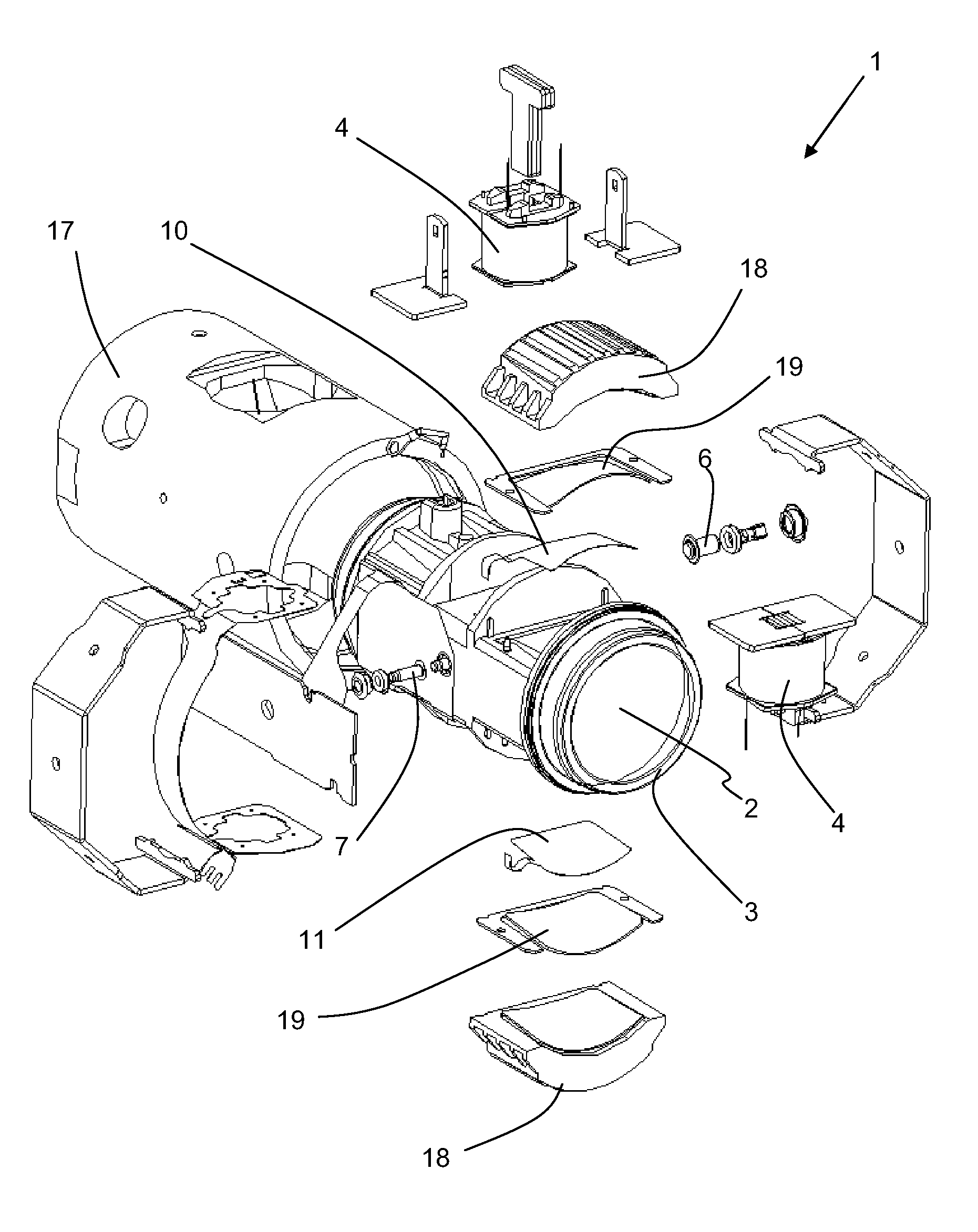
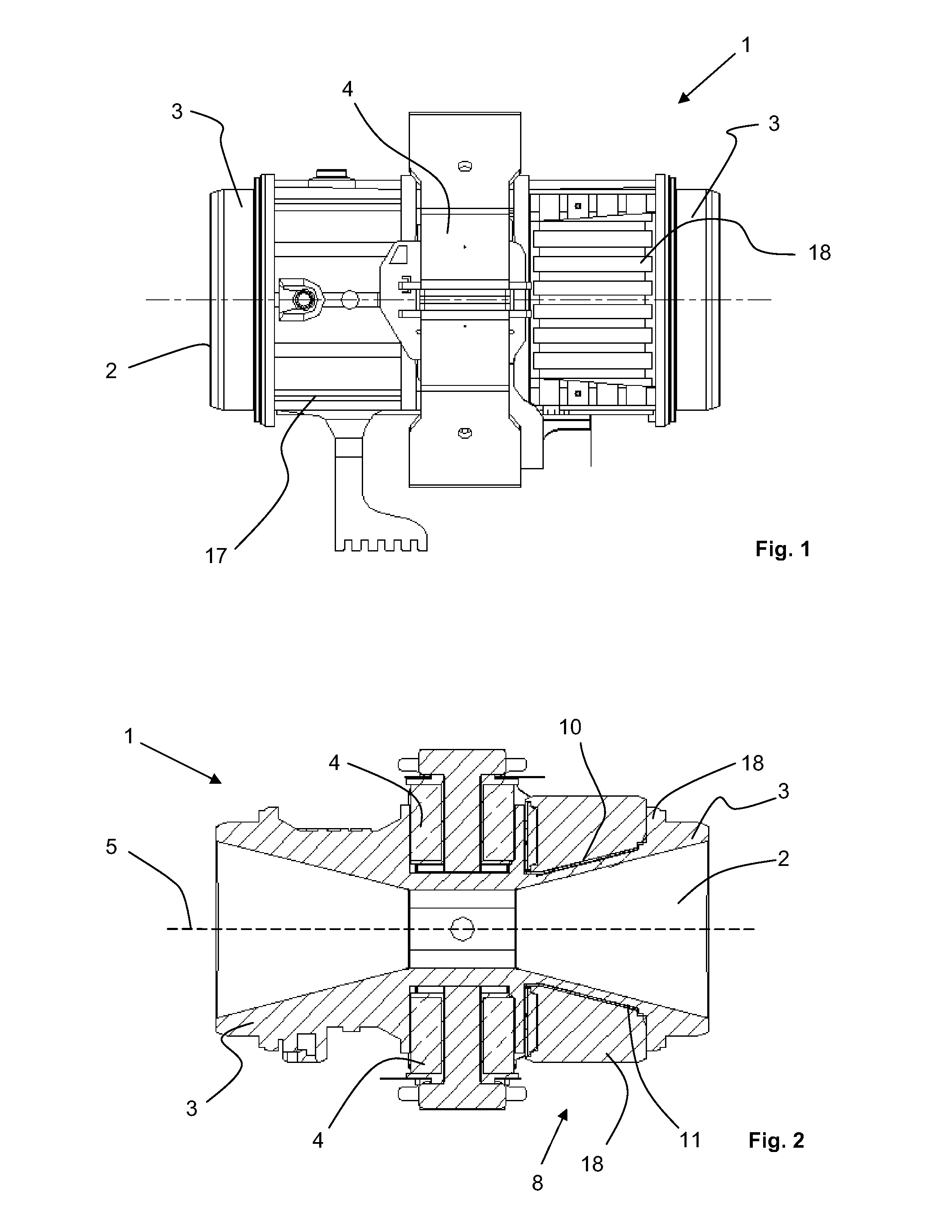
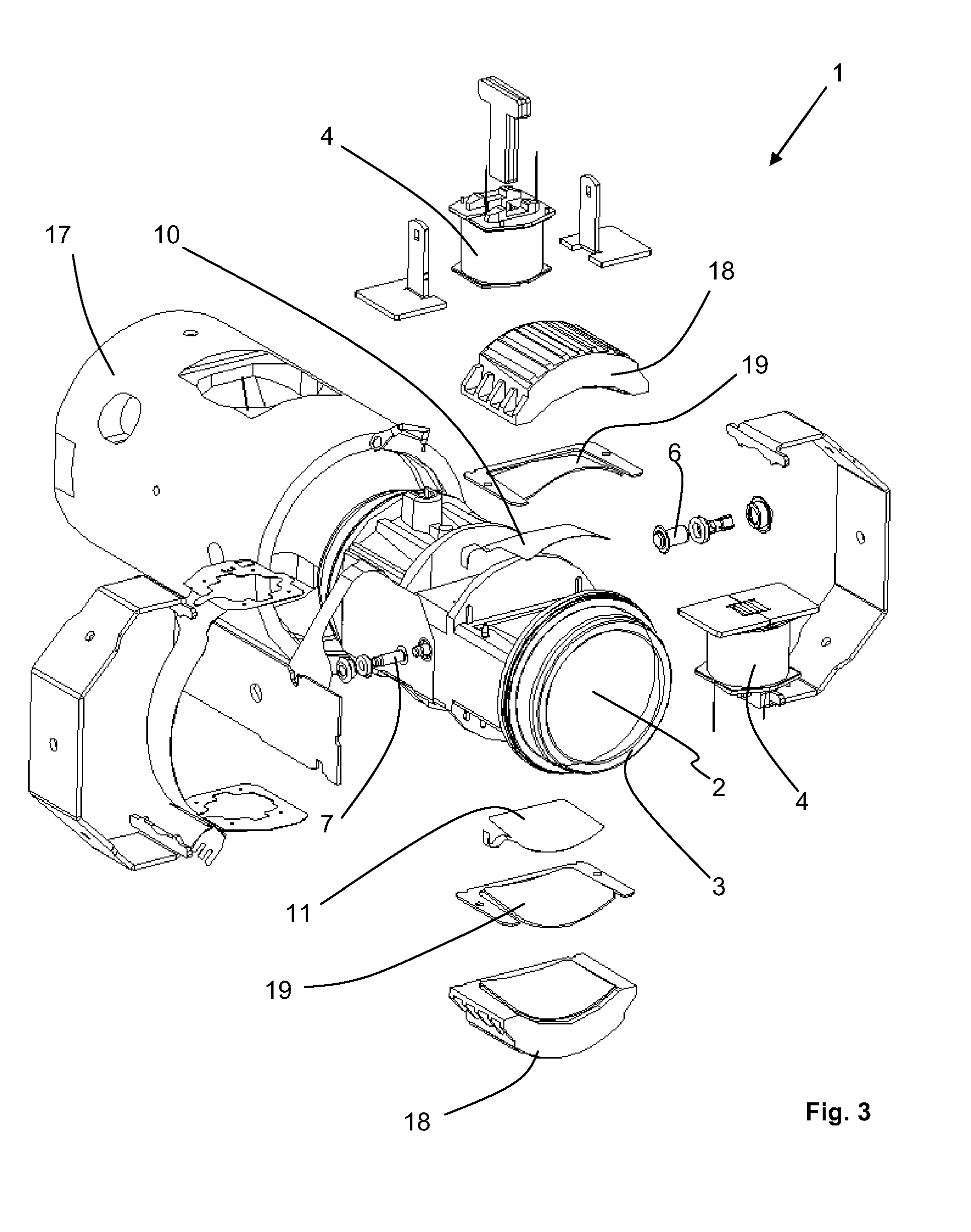
[0025]FIGS. 1 to 3 show a preferred embodiment of a magnetic inductive flow meter 1 according to embodiments of the present invention for measuring the flow of a flowing, conductive medium 2 in a measuring tube 3. In order to measure the flow of the medium 2, a magnetic field generating device is provided that has two coils 4, which are externally mounted on opposite sides on the measuring tube 3, and which are supplied with power by a current generator that is not shown here. The magnetic field generating device or, respectively, the coils 4 generate a magnetic field, which penetrates the measuring tube 3 essentially perpendicularly to the longitudinal axis 5 thereof. In addition, two measuring electrodes 6, 7 are also provided, which are galvanically coupled with the medium 2 and tap a measuring voltage that is induced in the flowing medium 2. Besides the galvanic coupling of the measuring electrodes 6, 7 with the medium 2 provided in this case, a capacitive coupling is also essen...


PUM


Abstract

A magnetoinductive flowmeter for measuring the flow rate of a flowing, conductive medium with a capacitive measuring apparatus for detecting empty pipes is provided. In order to improve the detection of empty pipes and, in particular, the capacitive coupling to the medium, the invention provides for the measuring apparatus for detecting empty pipes to comprise a sheet-like electrode in each case and a counterelectrode which form a measurement capacitance CMess which is dependent on the medium and on the degree of filling of the measuring tube; for the measuring tube to have a wall thickness which is reduced in order to maximize the measurement capacitance CMess at least in the region of the electrode and the counterelectrode; and for the measuring tube to be surrounded by a metal supporting housing, wherein, in order to maintain the pressure resistance of the measuring tube, a hollow-walled supporting body for minimizing the influence of parasitic capacitances on the measurement capacitance CMess is arranged in each case in the region of the reduced wall thickness between the electrode and the inner wall of the supporting housing and between the counterelectrode and the inner wall of the supporting housing and supports the measuring tube against the supporting housing in each case.

Description

CROSS-REFERENCE TO RELATED APPLICATION[0001]This application claims priority to PCT Application No. PCT / EP2013 / 065476, having a filing date of Jul. 23, 2013, based on DE 10 2012 213 507.3 filed Jul. 31, 2012, the entire contents of which are hereby incorporated by reference.FIELD OF TECHNOLOGY[0002]The following relates to a magnetic inductive flow meter for measuring the flow of a flowing, conductive medium.BACKGROUND[0003]Magnetic inductive flow meters, whose mode of operation is based on the principle of electromagnetic induction (=Faraday's law of induction), have been known for many years and are extensively being used in industrial measurement engineering. According to the law of induction, an electric field strength that is perpendicular to the direction of flow and perpendicular to the magnetic field is generated in a flowing medium, which is carrying charge carriers, that flows through a magnetic field. In magnetic inductive flow meters, the law of induction is exploited in...

Claims


Application Information

Patent Timeline
IPC IPC(8): G01F1/58
CPCG01F1/584G01F1/588G01F15/00G01F15/14
Inventor REICHART, WALTERKREISEL, CHRISTIANKRIESEN, RALFKORBER, MARKUSLIEHR, SEBASTIANHOCH, WERNER
Owner IMF ELECTRONIC GMBH
Learn More