
Wind turbine comprising a tower part of an ultra-high performance fiber reinforced composite

a technology of ultra-high-performance fibers and composites, which is applied in the direction of motors, solid waste management, sustainable waste treatment, etc., can solve the problems of high-performance materials used in the lower part of the tower subjected to a large torque, and achieve the effect of saving energy and reducing the cost of us

Inactive Publication Date: 2015-06-18
FORIDA DEV AS
View PDF1 Cites 7 Cited by
  • Summary
  • Abstract
  • Description
  • Claims
  • Application Information

AI Technical Summary

Benefits of technology

The present invention is about a new way to make wind turbine towers that are slimmer and lighter than traditional concrete towers. This is done by using an ultra-high performance fiber reinforced composite with a specific content of steel fibers. The resulting tower is made up of thin-walled segments that have a substantially reduced wall thickness compared to traditional concrete towers. The tower is designed with an upper steel tower part that takes up the stresses from gravity and shear forces, and a lower UHPFRC tower part that takes up the dominant torque from the wind. Each segment of the tower is made up of multiple wall sections with vertical connections, which allows for the efficient production and transportation of the tower segments to the construction site. The use of the UHPFRC with steel fibers allows for a slender construction, with a lower average wall thickness, which results in lower costs of manufacturing and transportation. This new design is also advantageous for a hybrid tower, where the upper steel part takes up the stresses from gravity and the rotor, while the lower UHPFRC tower part takes up the dominant torque from the wind.

Problems solved by technology

However, use of these materials for the lower part of the tower which is subjected to a large torque as discussed previously would have been disregarded because the tower construction required to sustain the torque and its consequences, in particular buckling of the tower wall, i.e. a wide diameter of the tower and high average wall thickness of the tower would not benefit from the advantageous characteristics of the composite material.
The use of such high performance materials would therefore be an expensive solution since the material is both costly in use and laborious to manufacture larger parts from.

Method used


Image

  • Wind turbine comprising a tower part of an ultra-high performance fiber reinforced composite
  • Wind turbine comprising a tower part of an ultra-high performance fiber reinforced composite
  • Wind turbine comprising a tower part of an ultra-high performance fiber reinforced composite

Examples


first embodiment

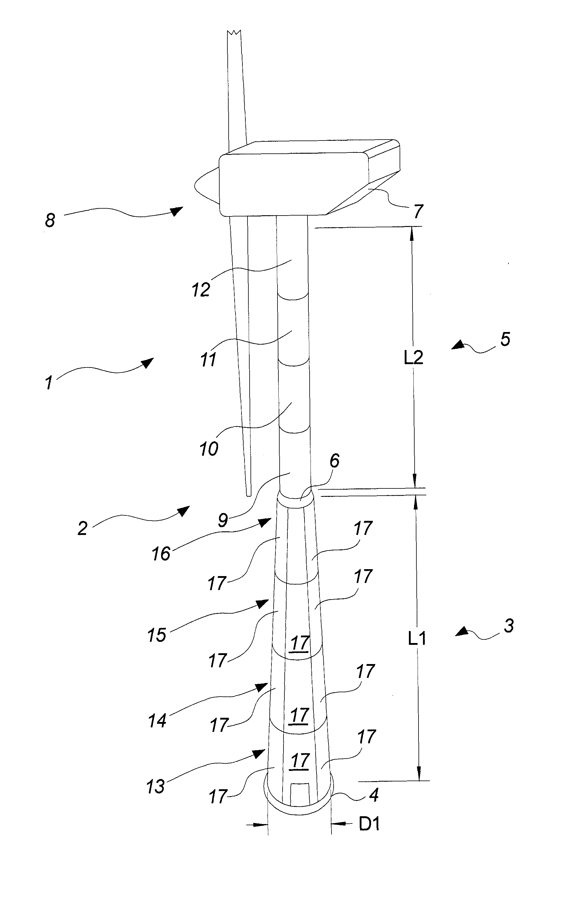
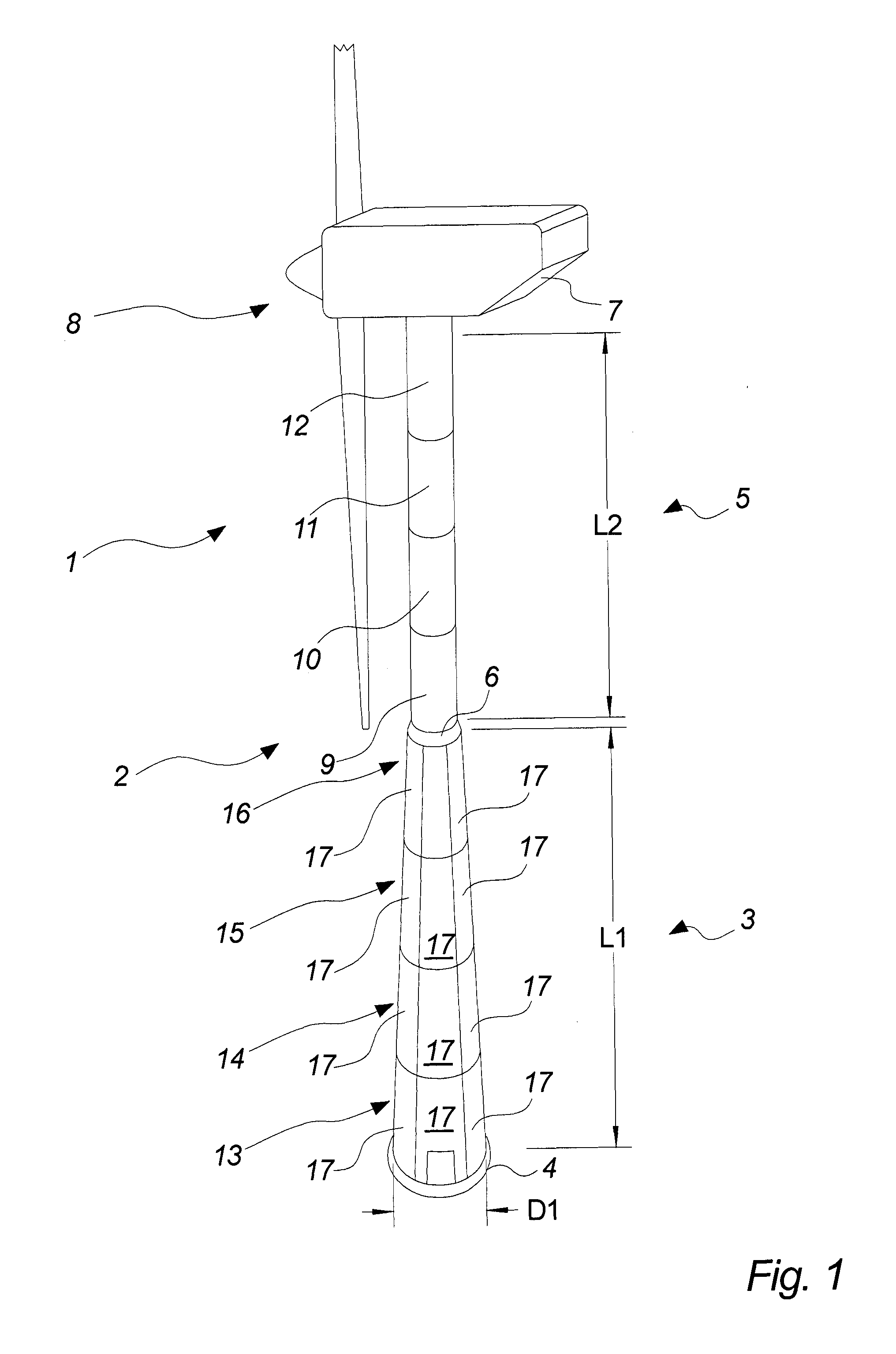
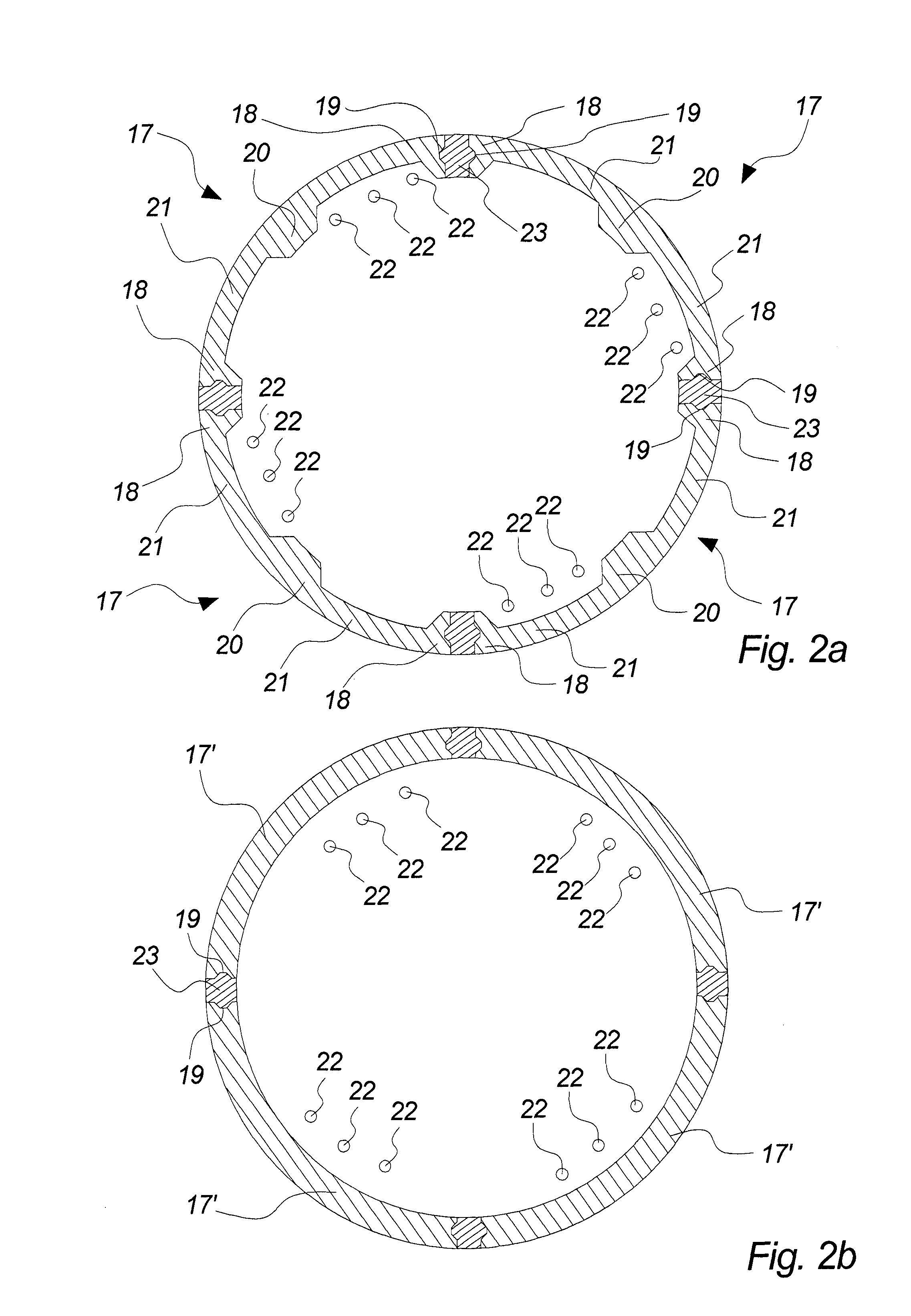
[0033]In the UHPFRC segments 13, 14, 15, 16 as shown in cross-section in FIG. 2a, the individual wall element 17 comprises two longitudinal flanges 18 and a central rib 20 extending longitudinally there between, the flanges 18 and the rib 20 having a first thickness in the radial direction of the segment 13, 14, 15, 16, i.e. in the direction from the centre of the segment 13, 14, 15, 16 and outwards, and the intermediate wall parts 21 having a second thickness in the radial direction being smaller than the first thickness. A typical value for the first thickness is in the range of 350 to 450 millimeter whereas a typical value for the second thickness is in the range of 50 to 80 millimeter. An average wall thickness of a cross-section of the segment may be calculated to be the wall thickness of a section having the same exterior peripheral shape of the segment, the same cross-sectional area of the wall and a uniform wall thickness. Such average wall thickness is preferably in the ran...

second embodiment

[0034]In an alternative second embodiment of the UHPFRC segments 13, 14, 15, 16 as shown in cross-section in FIG. 2b, the individual wall element 17′ is of a uniform thickness throughout the horizontal section, and that thickness is preferably in the range of 80 to 130 millimeters.

[0035]The segments 13, 14, 15, 16 of the UHPFRC part 3 of the tower 2 are pre-tensioned in the vertical direction by means of a set of pre-tensioning strands 22 extending from the foundation 4 or the lower part of the lowermost segment 13 to the transition piece 6 or to the top of the uppermost segment 16 or alternatively to the steel part 5 of the tower 2. The function of the pre-tensioning strands is to prevent that the total vertical compressive stress on the lower UHPFRC part 3 of the tower 2, i.e. the sum of the load from the aerodynamic forces on the wind turbine generator 1, mainly on the rotor 8 and the load from gravity forces becomes less than zero at any part of the lower part 3, that is to prev...


PUM

PropertyMeasurementUnit
Fractionaaaaaaaaaa
Fractionaaaaaaaaaa
Fractionaaaaaaaaaa

Abstract

A wind turbine generator (1) is disclosed comprising a nacelle (7) and rotor (8), and a tower (2, 3, 5) between said nacelle and a foundation (4), wherein said tower comprises an ultra-high performance fiber reinforced composite (UHPFRC) tower part (3) extending from the foundation (4) and including at least four tower segments (13, 14, 15, 16) arranged on top of each other to form a column, and pre-tensioning steel strands or bars (22) for pre-tensioning said tower segments (13, 14, 15, 16) in a vertical direction, wherein said UHPFRC tower part (3) is made in a UHPFRC with a percentage of steel fibers per volume in the range of 0.5 to 9, such as 1 to 6, and preferably in the range of 2 to 4.

Description

[0001]The present invention relates to a wind turbine generator comprising a nacelle and rotor, and a tower between said nacelle and a foundation, wherein said tower comprises a composite tower part extending from the foundation and including at least four tower segments arranged on top of each other to form a column.BACKGROUND[0002]Wind turbine towers have the purpose of supporting the nacelle carrying the rotor with normally two or three blades at an elevated position, where the influence of the ground on the wind speed is low. The tower must be designed for taking up the relevant stress during all operating and non-operating situations without being subject to failure or fatigue within the expected lifetime of the wind turbine. The relevant stress origins from act of gravity on the nacelle and the tower, from the shear forces from the aerodynamic drag force on the wind turbine rotor during operation of the wind turbine and from a torque on the tower due the action of said aerodyn...

Claims


Application Information

Patent Timeline
IPC IPC(8): F03D11/04E04H12/16F03D9/00
CPCF03D11/04E04H12/16F03D9/002Y02E10/728E04H12/08F05B2240/912F05B2280/6003F03D13/20F03D9/25E04H12/02Y02E10/72C04B28/04C04B2201/52Y02W30/91C04B14/062C04B14/48C04B18/08F03D9/34
Inventor JENSEN, LARS ROMKARLSEN, JAN
Owner FORIDA DEV AS
Learn More