Adjustable Roller Carrier

a roller carrier and adjustable technology, applied in the direction of rigid support of the bearing unit, soldering apparatus, welding devices with large diameter, etc., can solve the problems of limiting the application of roller carriers, roller carriers, and inability to stabilize and roll large diameter welding, etc., to achieve the effect of small horizontal adjustment of steel pipes, large lifting stroke, and convenient and fast rollers

Active Publication Date: 2015-06-18
CHENGDU ALANGTECH
View PDF10 Cites 5 Cited by
  • Summary
  • Abstract
  • Description
  • Claims
  • Application Information

AI Technical Summary

Benefits of technology

The invention provides an adjustable roller carrier that can adjust the distance and height of rollers, while being compact and space-efficient. This allows for rotating steel pipes in narrow spaces, lifting and transporting them by railway, and operating safely and conveniently in limited space. Additionally, the invention includes a steel pipe weldment with arc structure that has more contact area with the base, making it more accurate, convenient, and fast for the rollers to align. The weldment is also more stable when rotated on the arc structure base, particularly for larger diameter weldments. The invention also includes a hydraulic system with electric hydraulic pumps, hydraulic valves, and electromagnetic valves that allows for more convenient and efficient operation.

Problems solved by technology

Since all the existing adjustable roller carriers have defects of being large in structure and high in center height, manual or electric sliding plate adjustment structure causes the steel pipe to lift slowly; and the upper surface of the roller carrier base is horizontal, so weldment with large diameter is not stable and easy to roll when placed on the roller carrier.
Though, under special environment, such as inside a tunnel, the operation position and space are restricted strictly, the current roller carriers cannot meet the operation requirements, which limits the application of the roller carriers.

Method used


Image

  • Adjustable Roller Carrier
  • Adjustable Roller Carrier
  • Adjustable Roller Carrier

Examples


Embodiment Construction

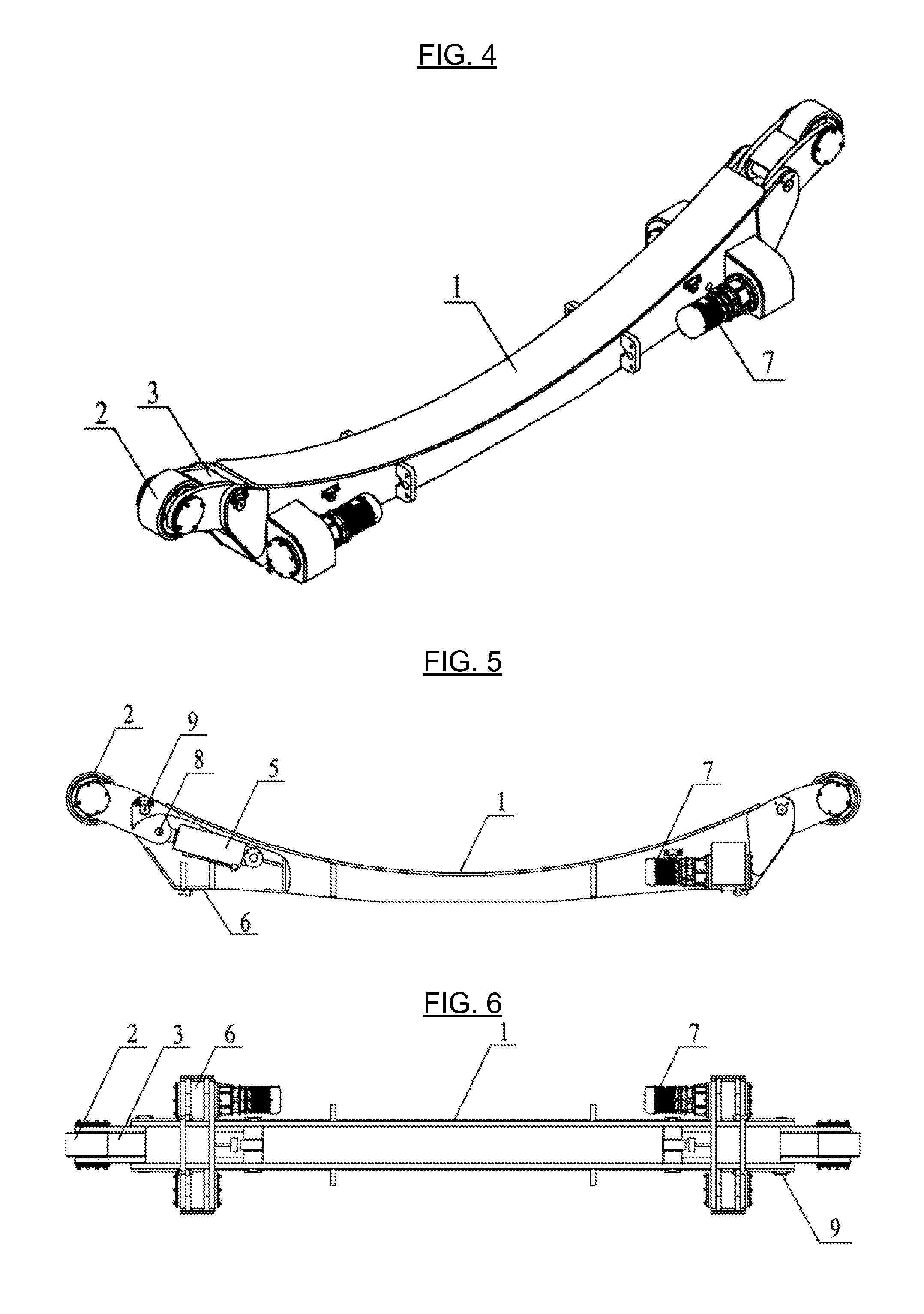
[0025]With the combination of the following drawings, the invention is described in details.

[0026]The invention will be further described in more details and the purposes, the technical solution and the advantages of the invention will be more apparent with the combination of the following drawings and embodiments. It shall be understood that the embodiments described herein are only used for explaining the invention but do not limit the invention.

[0027]An adjustable roller carrier as shown in FIG. 1-FIG. 6, among which FIGS. 1-3 are driving roller carrier, FIGS. 4-6 are driven roller carrier. An adjustable roller carrier comprising roller carrier base 1, roller 2 and electric motor speed reducing driver, wherein both ends of the roller carrier base 1 are each articulated with a roller bearing 3 and a roller carrier hydraulic jack 5, among which roller bearing 3 is the triangular articulated structure, roller carrier hydraulic jack 5 is articulated with roller bearing 3, roller 2 is...


PUM

PropertyMeasurementUnit
friction forceaaaaaaaaaa
diametersaaaaaaaaaa
diameteraaaaaaaaaa

Abstract

Disclosed is an adjustable roller carrier, comprising a roller carrier base (1), rollers (2) and a motor speed reducing driver, wherein both ends of the roller carrier base are each articulated with a roller bearing (3) and a roller carrier hydraulic jack (5), with the roller carrier hydraulic jack (5) being articulated with the roller bearing (3) and the roller (2) being mounted on the roller bearing. The roller carrier hydraulic jack and a hydraulic pump station thereof, and an electromagnetic valve are all placed inside a hollow roller carrier support so that not only the height and the centre-to-centre distance of the rollers are adjustable, but also the adjustable roller carrier has the advantages of being integrally compact in structure, and small in terms of occupied space. The adjustable roller carrier enables the steel pipe to rotate in a narrow space, can be fast lifted, and transported by railway. The adjustable roller carrier is convenient to operate and has high safety.

Description

TECHNICAL FIELD[0001]This invention relates to a roller carrier, especially an adjustable roller carrier.BACKGROUND[0002]A roller carrier is a device which drives the cylindrical (or conical) weldment to rotate by the friction force between the weldment and driving rollers. The roller carrier can be categorized into self-aligning type, adjustable type, flatcar type, inclinable type, anti-axial shifting type and etc., among which the adjustable roller carrier comprises a roller carrier base, driving roller components and driven roller components. Currently, the adjustable roller carrier has three types, including manual lead-screw adjustable type, manual bolt displacement type and electric sliding plate displacement type, which all of these are satisfied weldment with different diameters by adjusted the center-to-center distance of rollers manually. Since all the existing adjustable roller carriers have defects of being large in structure and high in center height, manual or electric...

Claims


Application Information

Patent Timeline
Patent Type & Authority Applications(United States)
IPC IPC(8): B23K37/053F16C35/04
CPCF16C35/042B23K37/0538B23K31/027B23K2101/06B23K2103/04
Inventor SHI, CHANGYUPENG, ZHIHUIPENG, ZHIXIANG
Owner CHENGDU ALANGTECH
Why Eureka
Try Eureka