Configurable interface circuit

a technology of interface circuit and configuration, applied in the field of interface circuit, can solve the problems of unsuitable interfaces for power parts operating using analog or high, and achieve the effects of reducing space and weight requirements, reducing the total number of interfaces, and reducing the size and weight requirements

Active Publication Date: 2015-06-11
DIEHL AEROSPACE GMBH
View PDF24 Cites 2 Cited by
  • Summary
  • Abstract
  • Description
  • Claims
  • Application Information

AI Technical Summary

Benefits of technology

[0008]The interface circuit offers the advantage that two power connections are present, which are configurable as power input or power output according to requirements and hence can be driven or read. Hence, by using a sufficient number of identical interface circuits according to the invention, precisely enough interfaces can be provided in an electrical system that the total number of inputs and outputs is covered. If necessary, a single power connection remains unused. This results in a reduction in the total number of interfaces on the system plane by virtue of the different use possibilities of the interface circuit which is versatile, that is to say useable in a versatile manner, and configurable. Thus, the interface resources are almost completely or completely utilized. Since an unused interface is present, if necessary, the space and weight requirement reduces, which is of great advantage in particular in aircraft technology, and hence also the costs for the system-wide interfaces. The interface circuit which can be used in a versatile manner or is configurable according to requirements is therefore used to drive loads or motors and to detect digital and analog signals. By virtue of the configurability, various functionalities can be realized as well as various ranges of values of generated or detected electrical variables.
[0009]By virtue of the configurability of the power connections, a desired functionality can be switched on any of the connections, which ensures a so-called “switch functionality”. In other words, signal routing within the interface circuit is possible.

Problems solved by technology

This is disadvantageous, for example for reasons of cost, resources, space and weight.
Such an interface is not suitable for power parts operating using analog or those with high power, for instance motors or the like.

Method used


Image

  • Configurable interface circuit
  • Configurable interface circuit
  • Configurable interface circuit

Examples


Embodiment Construction

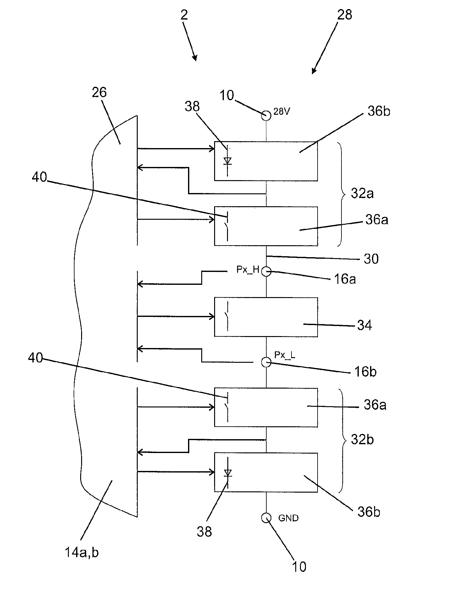
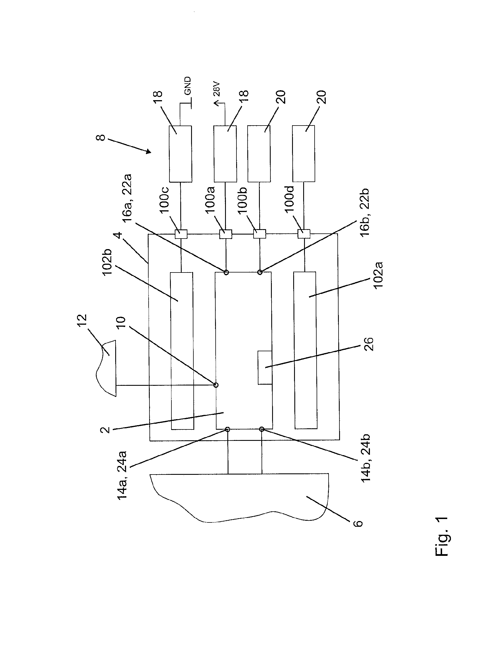
[0044]FIG. 1 shows an interface circuit 2 according to the invention in an interface module 4, which interface circuit is interconnected between a logic circuit 6 and a power circuit 8. The interface circuit is connected to a power supply 12 via a supply connection 10. Two logic connections 14a,b are used to connect to the logic circuit 6, two power connections 16a,b are used to connect to the power circuit 8 or to a load 18 and a switch 20. Therefore, the power connection 16a is configured as power output 22a and the power connection 16b is configured as power input 22b. The logic connection 14a is configured as logic input 24a for driving the load 18, the logic connection 14b is configured as logic output 24b for reading the switch 20. The configuration is done by the configuration unit 26.

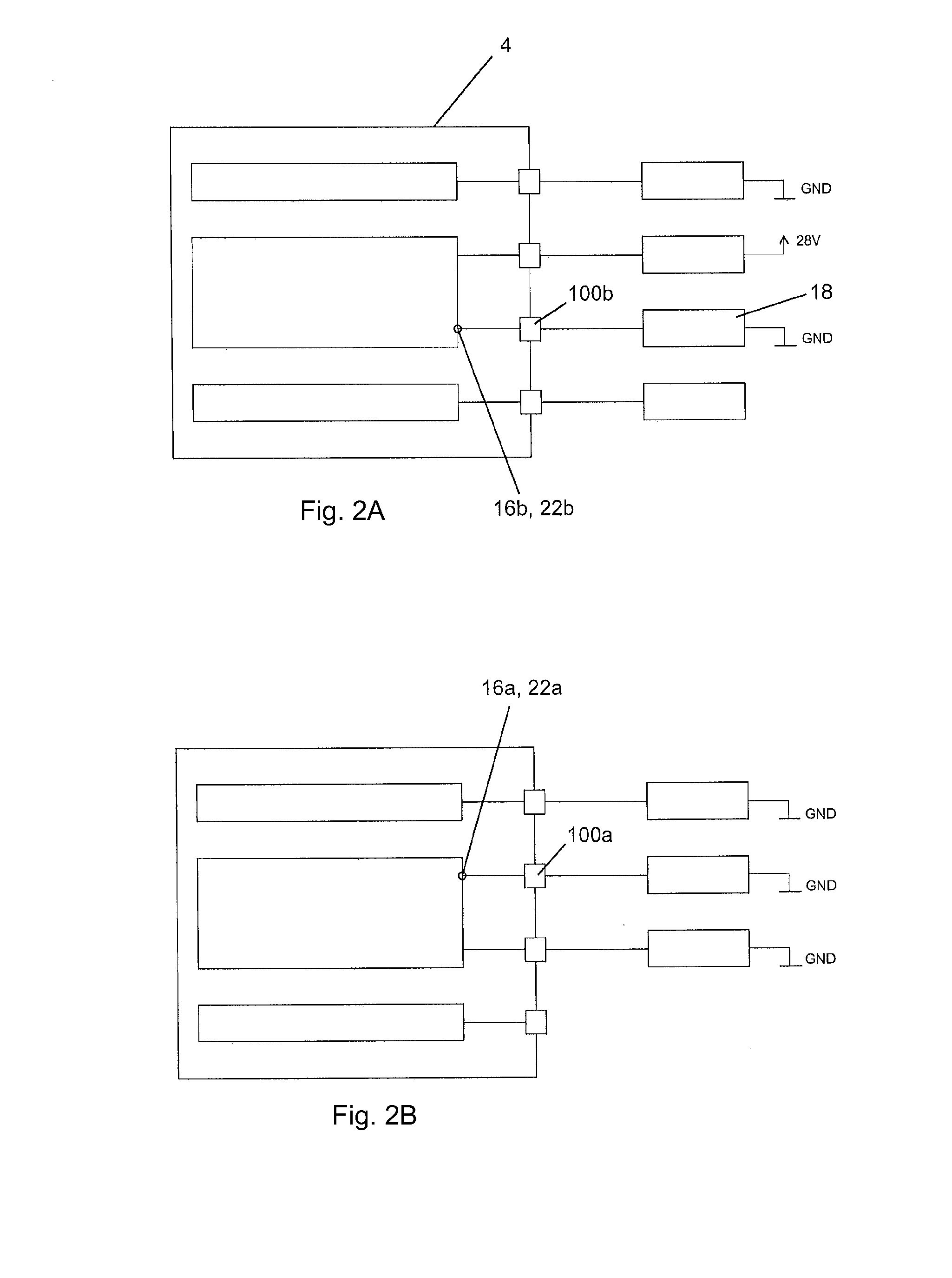
[0045]The interface module 4 also has power connections 100a-d. The power connections 16a,b of the interface circuit 2 are routed to the power connections 100a,b of the interface module 4.

[0046]...


PUM


Abstract

The present invention relates to an interface circuit for intermediate connection between a logic circuit and a power circuit, having a supply connection for connection to a power supply, contains two logic connections, which are configurable as logic input or logic output, and two power connections, which are configurable as power input or power output, and a configuration unit for the corresponding configuration, wherein the power input can be read by the logic output and the power output can be driven by the logic input.The present invention further relates to an interface module, having at least two power connections, contains at least one interface circuit, the power connections of which interface circuit are routed to the power connections of the interface module.

Description

BACKGROUND OF THE INVENTION[0001]The invention relates to an interface circuit—also referred to as interface—between a logic circuit (logic part of an electrical circuit) and a power circuit (power part of the circuit), in particular for use in an aircraft. The power part of the circuit is, for example, a load to be driven, for example a motor, which is then connected to a power output of the interface. Alternatively, it is an electrical element to be read, for example a switch the switch state of which is to be detected or a current conductor the current flow of which is to be measured, said electrical element then being connected to a power input of the interface. The interface is generally connected to a power supply in order to mutually transform logic signals, which are weak in terms of power, and load signals, which are intensive in terms of power.DISCUSSION OF THE PRIOR ART[0002]It is known to use specific DSO (discrete output) interfaces for the output functionality and to u...

Claims


Application Information

Patent Timeline
Patent Type & Authority Applications(United States)
IPC IPC(8): H03K17/687H02M1/38
CPCH02M1/38H03K17/6871G05B19/054H03K19/017581H03K19/01759H03K19/1733H03K2217/0036
Inventor SPAH, JURGEN
Owner DIEHL AEROSPACE GMBH
Why Eureka
Try Eureka