
Pixel circuit of display device, organic light emitting display device and method for driving the same

a display device and organic light technology, applied in the field of organic light emitting display devices, can solve the problems of deteriorating luminance and deteriorating picture quality of stereoscopic images, and achieve the effect of improving luminan

Inactive Publication Date: 2015-06-11
LG DISPLAY CO LTD
View PDF36 Cites 41 Cited by
  • Summary
  • Abstract
  • Description
  • Claims
  • Application Information

AI Technical Summary

Benefits of technology

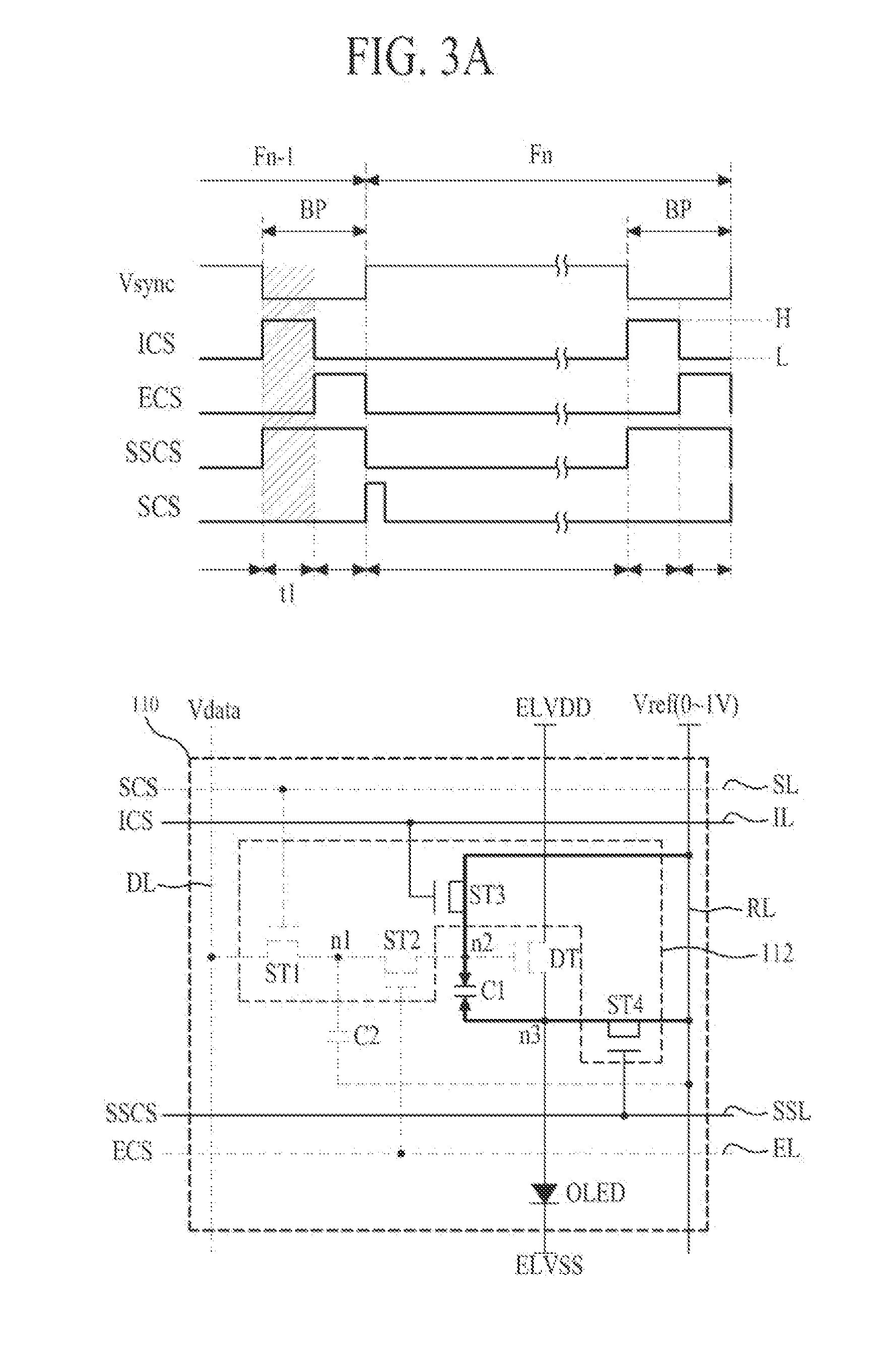
The present invention provides a pixel circuit and method for driving an organic light emitting display device that prevents picture quality degradation caused by crosstalk of left and right-eye images and improves luminance. This is achieved by simultaneously resetting the first capacitors of the pixels, charging a data voltage in the first capacitor for the second time period, and allowing the organic light emitting devices to simultaneously emit light and charge the data voltage of the next frame in the second capacitor. The technical effect of this invention is to improve the display quality of organic light emitting display devices.

Problems solved by technology

Although this stereoscopic image display device of the liquid crystal shutter mode provides a stereoscopic effect by separating the left-eye image from the right-eye image, the stereoscopic image display device has a problem in that picture quality of a stereoscopic image is deteriorated due to crosstalk that allows a viewer to perceive a ghost image of the left-eye image and the right-eye image.
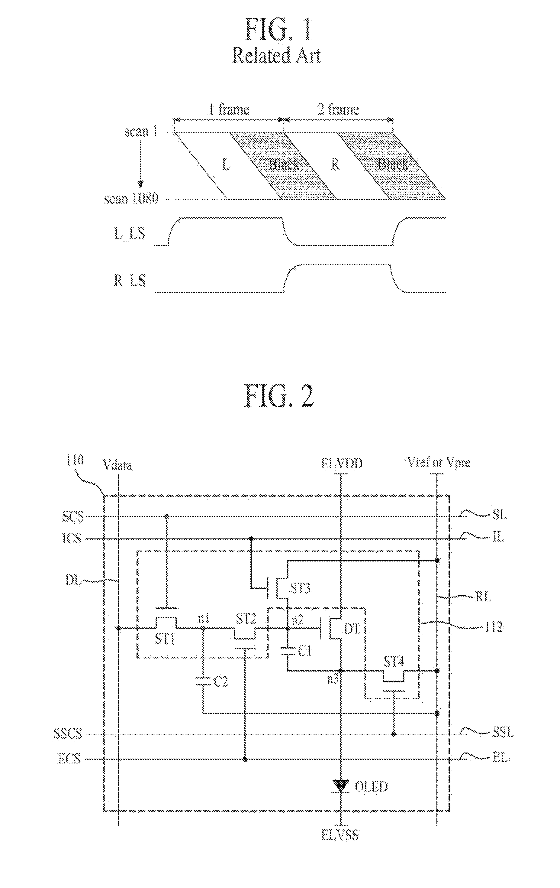
However, the stereoscopic image display device of the liquid crystal shutter mode, to which the black frame insertion technique is applied, has a problem in that luminance is deteriorated due to the black image inserted between every left-eye image L and every right-eye image R.

Method used


Image

  • Pixel circuit of display device, organic light emitting display device and method for driving the same
  • Pixel circuit of display device, organic light emitting display device and method for driving the same
  • Pixel circuit of display device, organic light emitting display device and method for driving the same

Examples


Embodiment Construction

[0027]Reference will now be made in detail to the exemplary embodiments of the present invention, examples of which are illustrated in the accompanying drawings. Wherever possible, the same reference numbers will be used throughout the drawings to refer to the same or like parts.

[0028]Terminologies disclosed in this specification should be understood as follows.

[0029]It is to be understood that the singular expression used in this specification includes the plural expression unless defined differently on the context. The terminologies such as “first” and “second” are intended to identify one element from another element, and it is to be understood that the scope of the present invention should not be limited by these terminologies.

[0030]Also, it is to be understood that the terminologies such as “include” and “has” are intended so as not to exclude the presence or optional possibility of one or more features, numbers, steps, operations, elements, parts or their combination. Furtherm...


PUM


Abstract

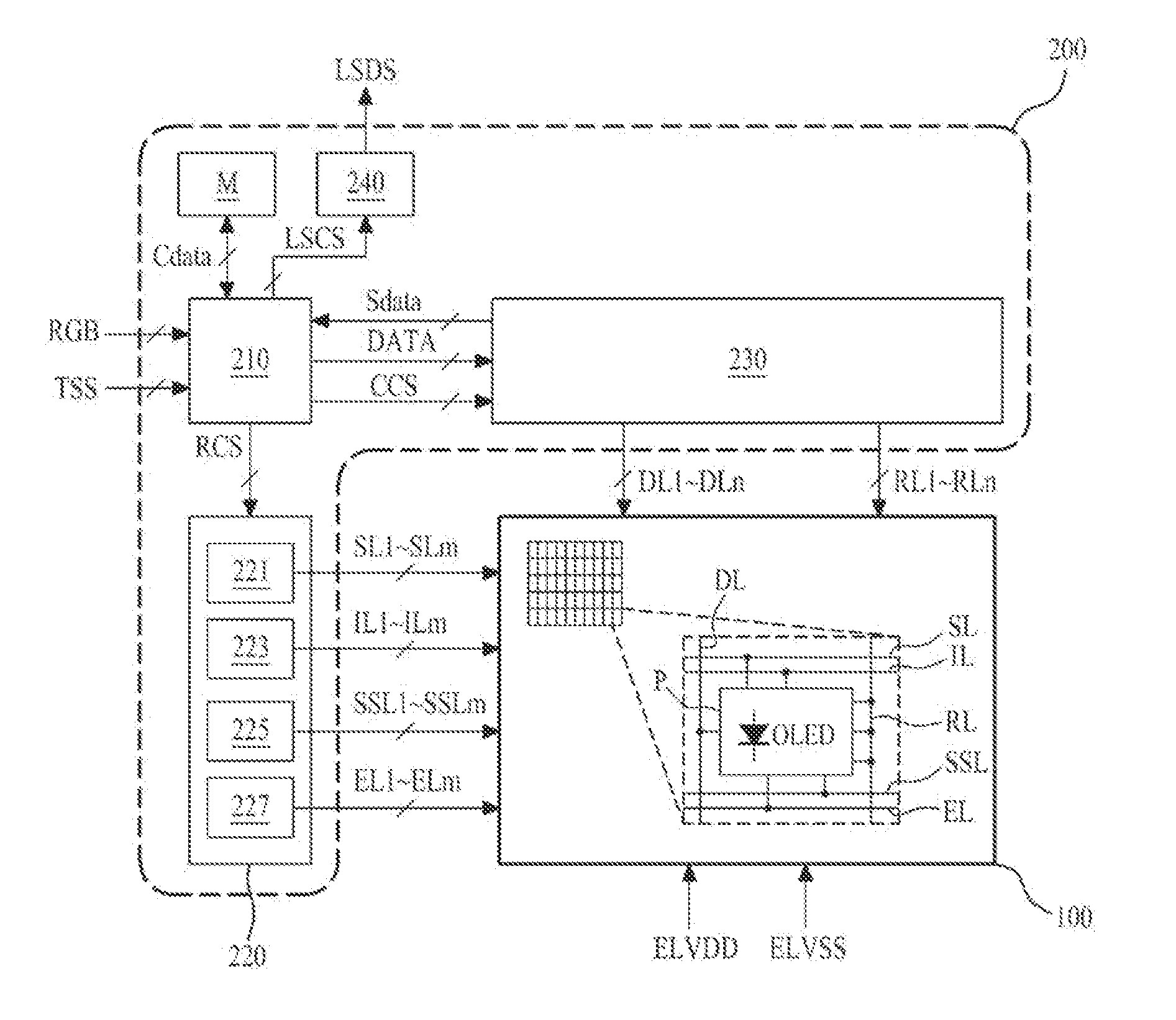
A pixel circuit of a display device, an organic light emitting display device and a method for driving the same are discussed. The pixel circuit of the display device in one example includes an organic light emitting device emitting light through a current; a driving transistor controlling the current flowing in the organic light emitting device; a first capacitor connected between gate and source electrodes of the driving transistor; a second capacitor in which a data voltage is previously stored; and a switching unit charging the data voltage, which is stored in the second capacitor, in the first capacitor, and allowing the organic light emitting device to emit light by driving the driving transistor in accordance with the data voltage charged in the first capacitor and at the same time charging a data voltage of next frame in the second capacitor.

Description

CROSS REFERENCE TO RELATED APPLICATIONS[0001]This application claims the priority benefit of the Korean Patent Application No. 10-2013-0154021 filed on Dec. 11, 2013, which is hereby incorporated by reference for all purposes as if fully set forth herein.BACKGROUND OF THE INVENTION[0002]1. Field of the Invention[0003]The present invention relates to an organic light emitting display device, and more particularly, to an organic light emitting display device that may improve luminance while preventing picture quality from being deteriorated.[0004]2. Discussion of the Related Art[0005]A stereoscopic image display device allows a left-eye image and a right-eye image, which have binocular parallax, to be separated from each other and be displayed respectively for a left eye and a right eye of a viewer. In other words, the stereoscopic image display device allows the right-eye image to be perceived by only the right eye of the viewer and allows the left-eye image to be perceived by only t...

Claims


Application Information

Patent Timeline
IPC IPC(8): G09G3/32
CPCG09G3/325G09G2320/0214G09G2310/0251G09G2300/0819G09G2300/0876G09G3/003G09G3/3241G09G2300/0809G09G2300/0852G09G2300/0861G09G2310/0262H04N13/30G09G3/32
Inventor WOO, DONG KYUNKIM, GI-HONG
Owner LG DISPLAY CO LTD
Learn More