
Thermal container, thermal liner for same and dies for making the thermal liner

a technology of thermal liner and container, applied in the field of thermal containers, can solve the problems of increasing waste, material loss, and reducing the efficiency of material removal from rectangular blanks,

Inactive Publication Date: 2015-06-11
FRESH BAILIWICK
View PDF3 Cites 26 Cited by
  • Summary
  • Abstract
  • Description
  • Claims
  • Application Information

AI Technical Summary

Benefits of technology

The patent describes a thermal liner for a container that includes a bottom panel, medial end panels, side panels, and end flaps. The liner also includes a top sheet and bottom sheet with a core in between. The liner is made up of cellulosic fiber based structures that are honeycomb-shaped cells. The liner is designed to insulate the container and keep the contents hot or cold. The liner is hinged at the medial end panels and side panels, allowing for easy folding and detachment. The liner can also be folded along a diagonal when not in use. The container also includes at least two container flaps that can be closed to secure the container. The technical effects of the thermal liner include improved insulation, easy folding and detachment, and secure closing of the container.

Problems solved by technology

Such removal of sections of material from a rectangular blank is not cost efficient and environment friendly as it causes loss of material and increases waste.
Moreover, in some cases the insulation properties of the resulting thermal container has proved unsatisfactory to maintain the goods in a refrigerated state for sufficient time periods.

Method used


Image

  • Thermal container, thermal liner for same and dies for making the thermal liner
  • Thermal container, thermal liner for same and dies for making the thermal liner
  • Thermal container, thermal liner for same and dies for making the thermal liner

Examples


Embodiment Construction

[0054]In the following description, the same numerical references refer to similar elements. The embodiments, geometrical configurations, materials mentioned and / or dimensions shown in the figures or described in the present description are preferred embodiments only, given solely for exemplification purposes.

[0055]Moreover, although the embodiments of the thermal container, the thermal liner for such a container and the die for making the thermal liner consist of certain geometrical configurations and components, as explained and illustrated herein, not all of these components and geometries are essential and thus should not be taken in their restrictive sense. It is to be understood, as also apparent to a person skilled in the art, that other suitable components and cooperation thereinbetween, as well as other suitable geometrical configurations, may be used, as will be briefly explained herein and as can be easily inferred herefrom by a person skilled in the art. Moreover, it wil...


PUM

PropertyMeasurementUnit
Thicknessaaaaaaaaaa

Abstract

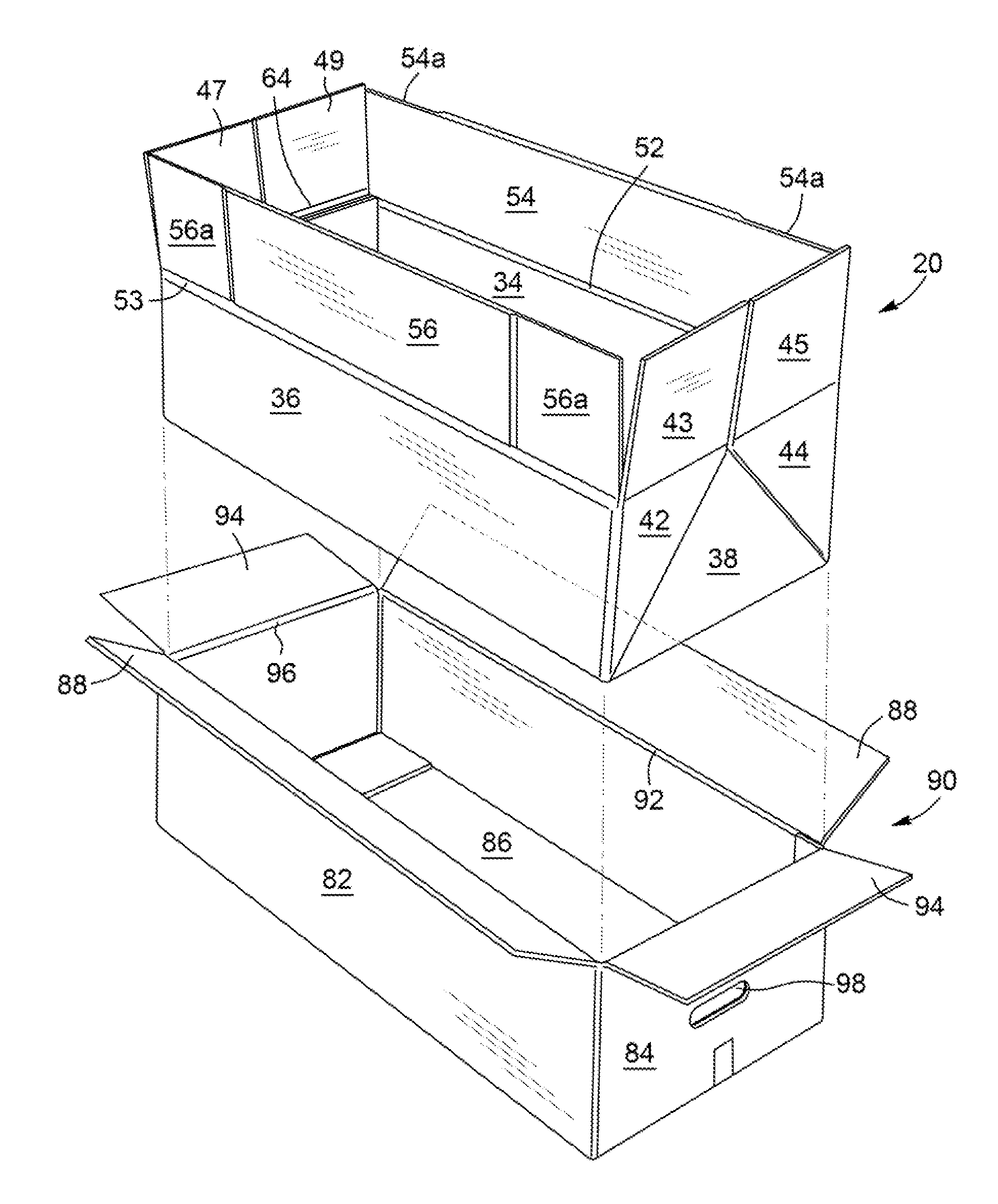
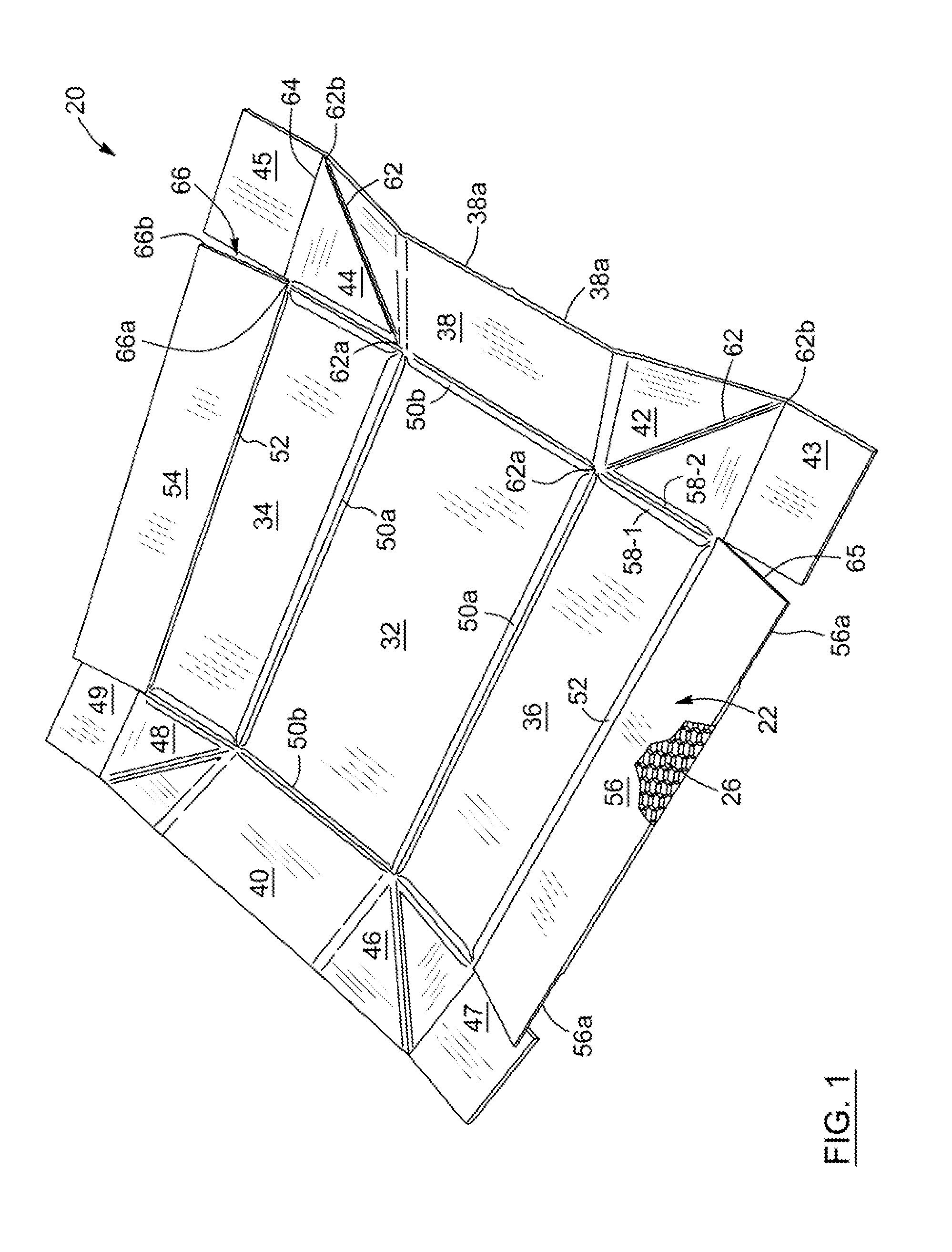
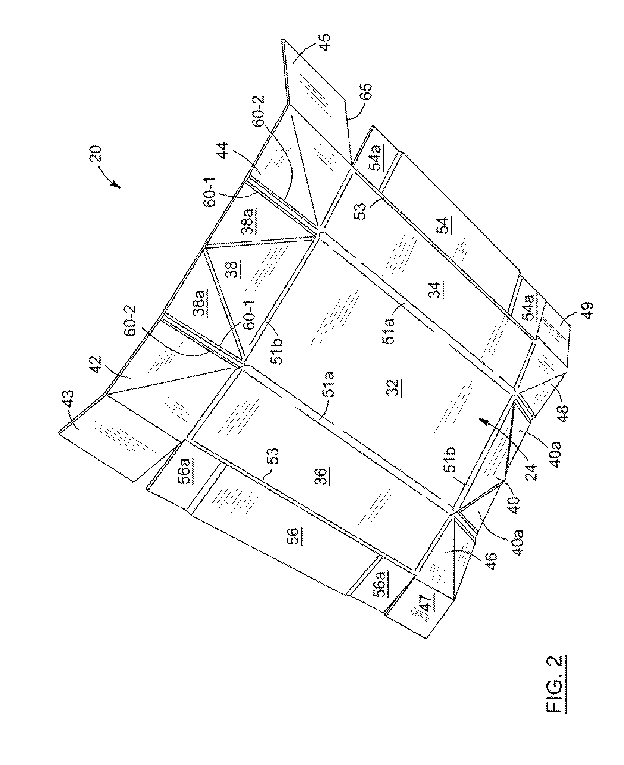
A thermal liner for a container comprises a bottom panel hingedly connected to a pair of opposed medial end panels and a pair of opposed side panels; four outer end panels each being hingedly connected along a first edge to a corresponding side panel and along a second edge to a corresponding medial end panel and being foldable along a diagonal thereof; a pair of opposed side flaps each being hingedly connected along an edge to a corresponding side panel; and end flaps hingedly connected along a first edge to one of a corresponding outer end panel or a corresponding side flap and having a free edge adjacent to the other one of the corresponding end panel or the corresponding side flap. There is also provided a thermal container comprising such a liner and a pair of dies for forming the thermal liner are also described.

Description

CROSS REFERENCE TO RELATED APPLICATION[0001]This application claims the benefit under 35 U.S.C. §119(e) of Provisional Application Ser. No. 61 / 913,606 filed Dec. 9, 2013 which is hereby incorporated by reference in its entirety.FIELD OF THE INVENTION[0002]This invention relates to thermal containers. More particularly, it relates to a thermal container, a thermal liner for such a container, as well as dies for forming the thermal liner.BACKGROUND[0003]It is known in the art to use materials such as waxed corrugate and honeycomb material covered by an aluminum foil layer or a metallized film layer in the manufacture of foldable thermal liners insertable into a box to form a thermal container used for packing perishable goods for temporary storage and / or shipping thereof. In order to maintain the perishable goods in a refrigerated state, a refrigerant such as ice, frozen gel packs or the like is usually placed in the thermal container along with the goods.[0004]For example, it is know...

Claims


Application Information

Patent Timeline
IPC IPC(8): B65D81/38B65D5/56B31B3/14
CPCB65D81/3818B31B2241/00B65D5/566B31B3/14B65B55/00B65D81/3858B31B50/142B31B50/252B31B2100/0024B31B2110/35B31B2100/00B31B50/14
Inventor MCKINNON, ALAN
Owner FRESH BAILIWICK
Learn More