
Roll formed step rail for a vehicle

a technology for vehicle body parts and step rails, which is applied in the direction of whips, candle holders, lighting support devices, etc., can solve the problems of rails affecting the surface finish, affecting the safety of passengers, and parts being rejected

Inactive Publication Date: 2008-04-22
IRON CROSS AUTOMOTIVE
View PDF8 Cites 56 Cited by
  • Summary
  • Abstract
  • Description
  • Claims
  • Application Information

AI Technical Summary

Problems solved by technology

However, the bending, stamping and extrusion processes conventionally used in forming step rails tend to mar, distort or otherwise damage the surface finish during forming.
But for top-quality parts, even minor surface finish imperfections may cause the part to be rejected.
Thus, the cost savings achieved by pre-finishing the stock may be lost due to a high defect rate in the finished product.
However, ordinary variation in the location of the mounting holes provided on the vehicle by its manufacturer can sometimes make it difficult to install and adjust the step rails without requiring “field modification” of the bracket system and / or step rail itself.
Such modifications are undesirable as they introduce additional complexity (and hence, additional cost) to the step rail mounting.
Further, if done improperly, such modifications may also affect the structural integrity of the step rail.

Method used


Image

  • Roll formed step rail for a vehicle
  • Roll formed step rail for a vehicle
  • Roll formed step rail for a vehicle

Examples


Embodiment Construction

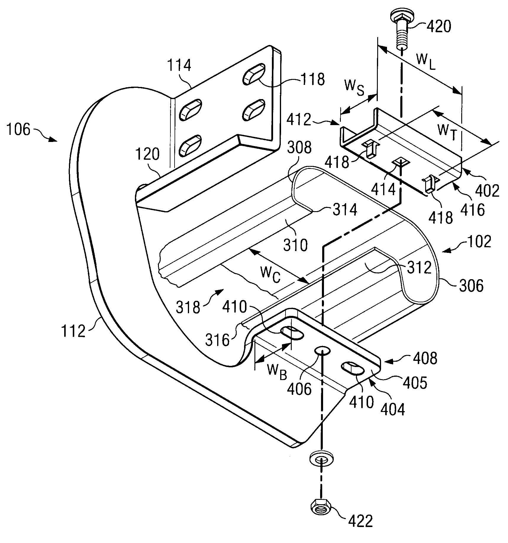
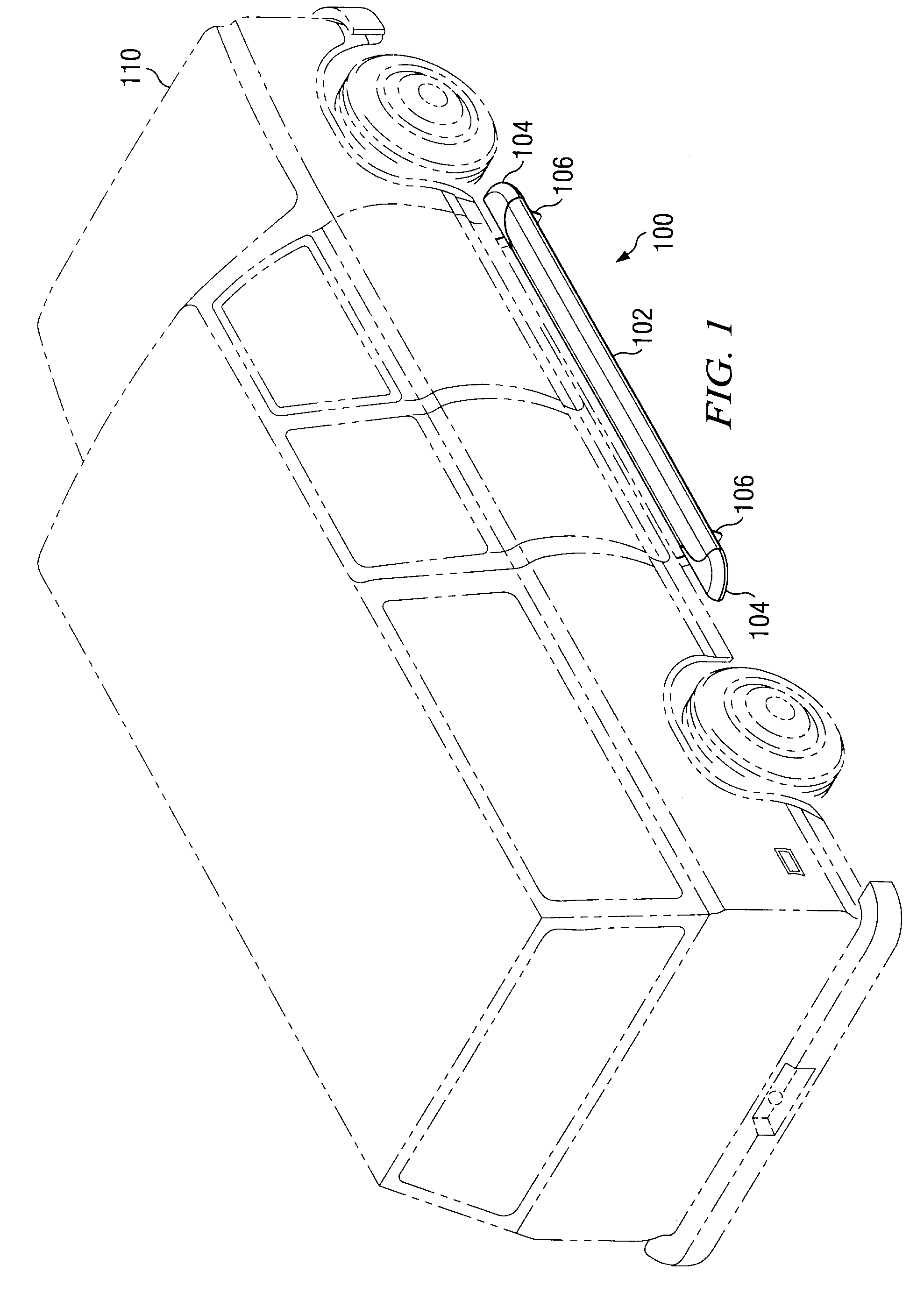
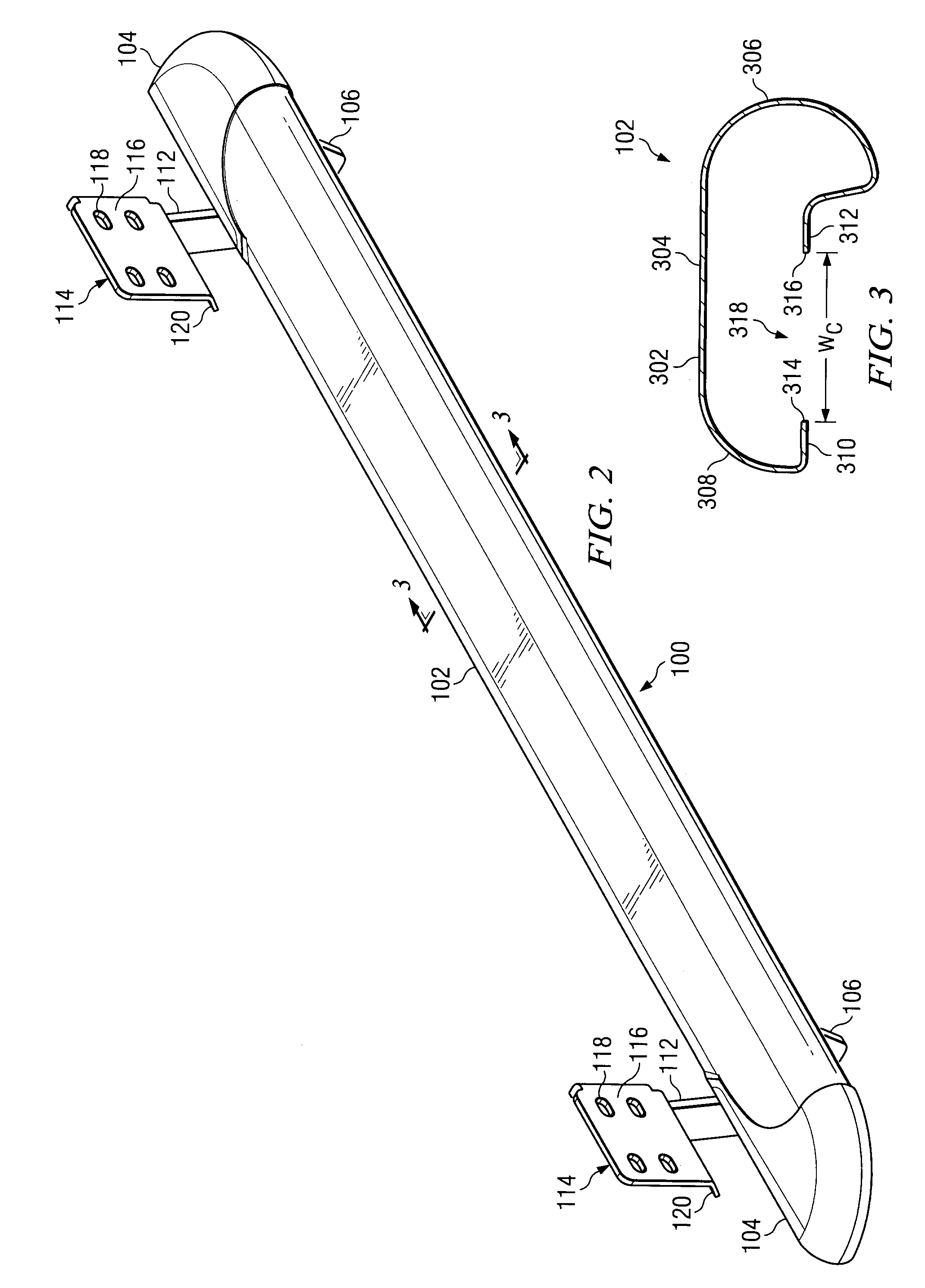
[0050]Referring now to the drawings, wherein like reference numbers are used herein to designate like elements throughout the various views, embodiments of the present invention are illustrated and described, and other possible embodiments of the present invention are described. The figures are not necessarily drawn to scale, and in some instances the drawings have been exaggerated and / or simplified in places for illustrative purposes only. One of ordinary skill in the art will appreciate the many possible applications and variations of the present invention based on the following examples of possible embodiments of the present invention.

[0051]Referring now to FIG. 1, there is illustrated one embodiment of a roll formed step rail for a vehicle in accordance with the current invention. The step rail 100 includes a rail body 102 and end caps 104. A bracket system 106 is used to attach the step rail 100 to the side of the vehicle 110 (shown in phantom). The bracket system 106 is normal...


PUM


Abstract

A roll formed step rail for a vehicle comprises an elongated rail body including a continuous rail wall of substantially uniform thickness. The rail wall describes a continuous cross-sectional profile between two elongated free edges, the cross-sectional profile of the rail being substantially uniform along the length of the rail body. The cross-sectional profile of the rail body includes a relatively flat top portion disposed between a substantially semi-circular front curved portion and a substantially quarter-circular rear curved portion. A rear mounting lip extends forward from the rear curved portion to one of the elongated free edges. A front mounting lip extends upward and then rearwards from the front curved portion to another of the elongated free edges. The elongated free edges are generally in line with one another, but spaced apart to define a longitudinal channel therebetween having a predetermined width. The rail body is formed from a sheet of material by a process of roll forming.

Description

CROSS-REFERENCE TO RELATED APPLICATIONS[0001]This application claims the benefit of priority from U.S. Provisional Application No. 60 / 741,522 filed Dec. 1, 2005.TECHNICAL FIELD OF THE INVENTION[0002]This invention is related to automotive vehicle body / chassis accessories such as running boards, side bars and tube steps, and more particularly, to step rails manufactured using a roll forming process for mounting on the sides of vehicles such as pickup trucks and sport utility vehicles.BACKGROUND OF THE INVENTION[0003]It is well known to mount body / chassis accessories such as running boards, side bars or tube steps (referred to collectively herein as “step rails”) below the side doors of automotive vehicles such as pickup trucks and sport utility vehicles (SUVs) to provide a convenient step for use when entering / exiting the vehicle and for protection of the vehicle against side body damage. In addition, these step rails frequently serve as styling members intended to personalize or enh...

Claims


Application Information

Patent Timeline
Patent Type & Authority Patents(United States)
IPC IPC(8): B60R3/00A47B96/06B62D25/18F21V21/00F16B7/04A47F5/08B60C9/00
CPCB60R3/002Y10T403/75Y10T403/1624Y10T403/1616
Inventor CRANDALL, ROBERT T.
Owner IRON CROSS AUTOMOTIVE
Learn More