Dental implant system with ceramic implant

a technology of ceramic implants and implants, applied in dental implants, dental surgery, medical science, etc., can solve the problems of brittle ceramic materials, disadvantages more expensive manufacturing methods of ceramic implant systems, so as to improve the effect of the dental implant system

Active Publication Date: 2015-05-28
Z SYST SCHWEIZ
View PDF4 Cites 20 Cited by
  • Summary
  • Abstract
  • Description
  • Claims
  • Application Information

AI Technical Summary

Benefits of technology

The invention is a dental implant system with a ceramic implant and an abutment that is improved compared to existing systems. The ceramic implant has a recess with an inner cone widening in the proximal direction. The abutment is connected to the ceramic implant in a friction fit, which reduces stress on the connection. The system is cost-effective and easy to manufacture. The ceramic implant is shielded from the body tissue, and the insert element, which can be made of metal or plastic, is enclosed in ceramic material. A spring element can be used to further reinforce the connection. This dental implant system has excellent characteristics and can be used for biocompatibility and aesthetics.

Problems solved by technology

Ceramic materials, however, are brittle, which is why ceramic implants are more prone to breakage as compared to implants manufactured from ductile, metallic materials.
The more costly manufacturing method of ceramic implant systems is also disadvantageous compared, for example, to implant systems of titanium or titanium alloys.
In particular, the machining of ceramic blanks, which is necessary in order to provide ceramic implant parts with the desired inner and outer structures, is time-consuming and costly.
Ceramic material, for example, cannot be turned or embossed due to the brittle characteristics.
The manufacture of delicate inner structures with grinding methods is particularly time-consuming.

Method used


Image

  • Dental implant system with ceramic implant
  • Dental implant system with ceramic implant
  • Dental implant system with ceramic implant

Examples


Embodiment Construction

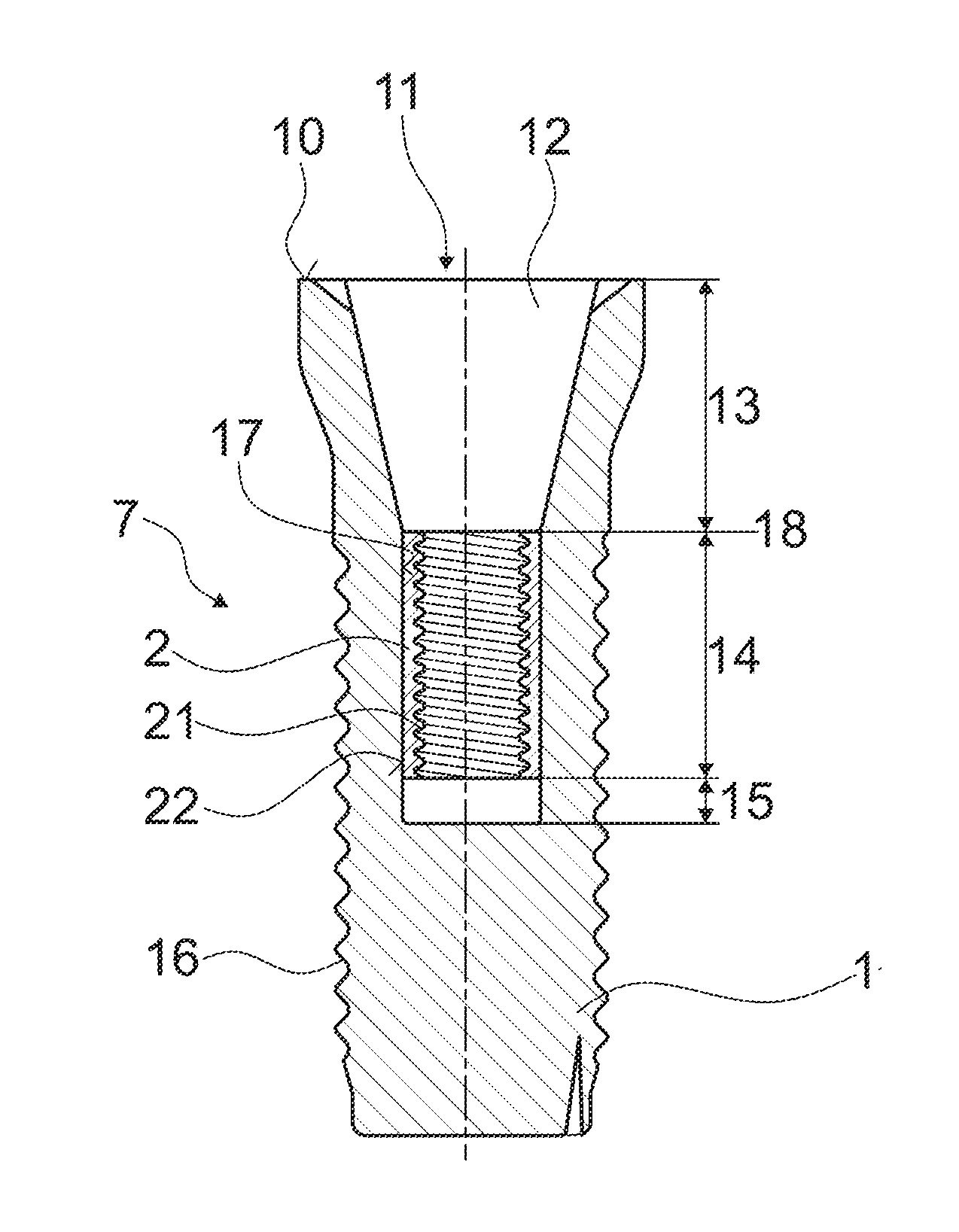
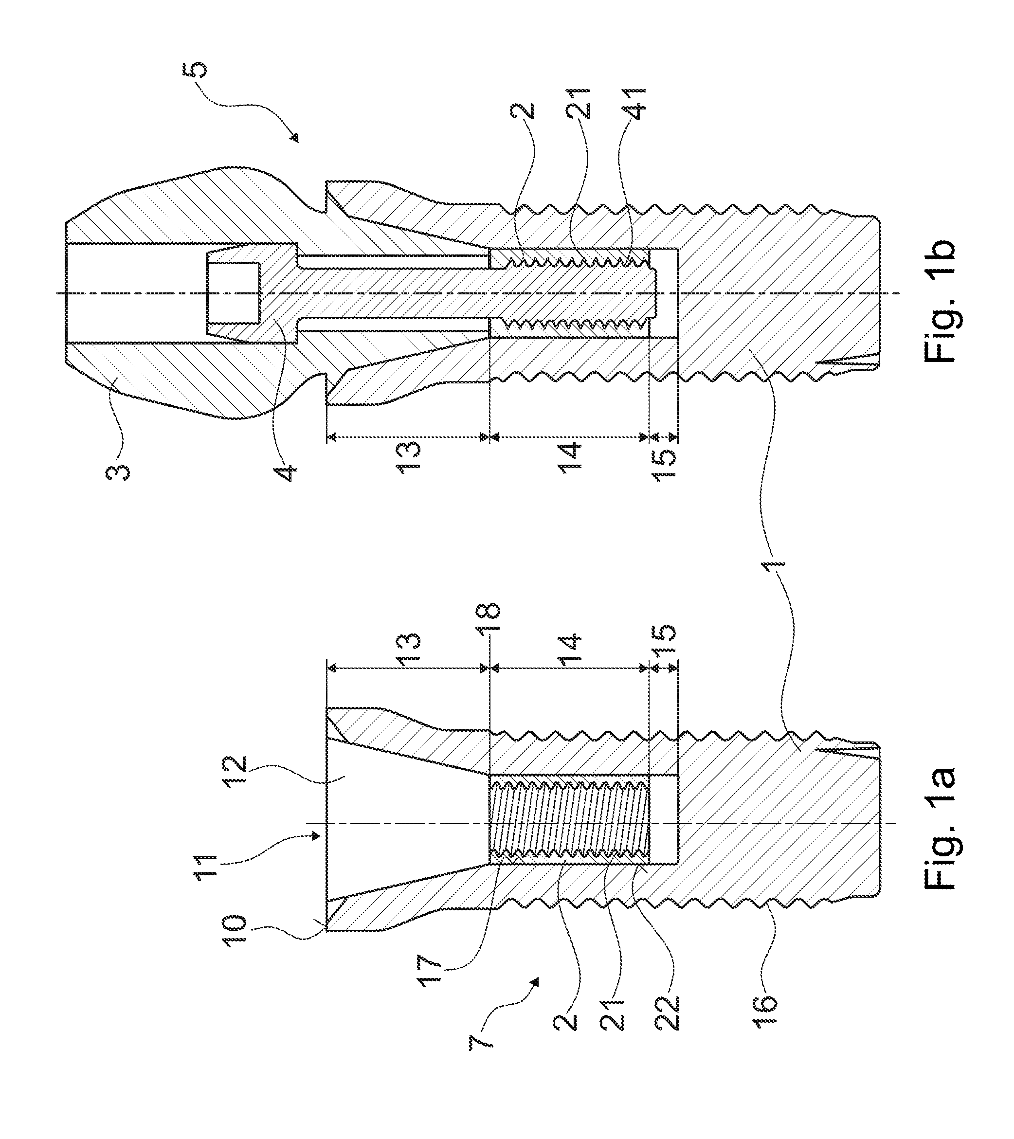
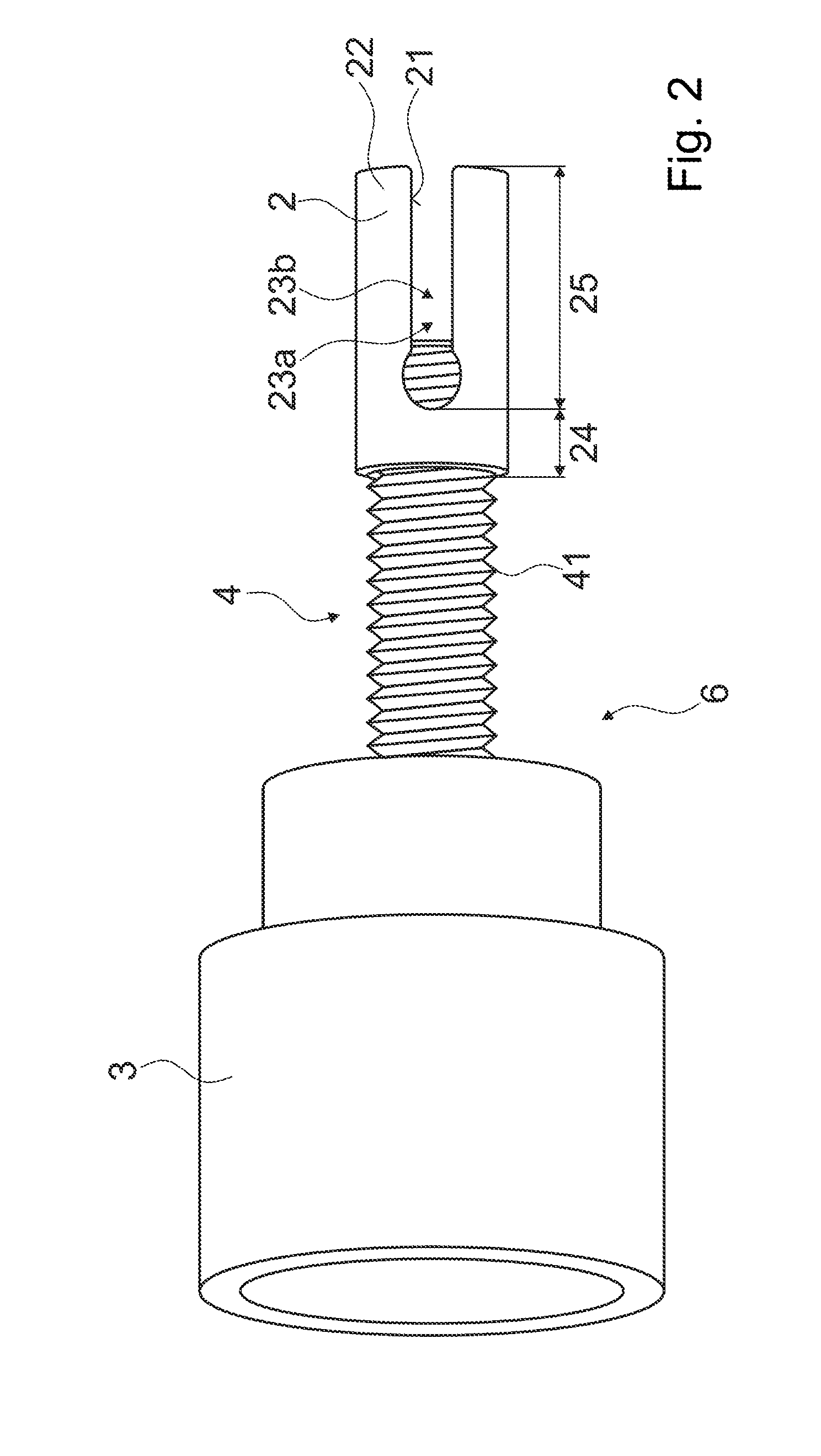
[0075]FIGS. 1a-1b show an exemplary dental implant system 5. A set 7 with a ceramic implant 1, which is essentially implanted into the bone, and with an inserted insert element 2 are shown in FIG. 1a. The exemplary dental implant system is shown in the connected condition with the ceramic implant 1, the insert element 2, an abutment 3 and an abutment screw 4 in FIG. 1b. The exemplary ceramic implant 1 has a proximal region with a recess 11 with a proximal opening 12. The recess 11 in the axial direction includes three sections: a proximal section 13, an insert section 14 and a distal end section 15. The exemplary ceramic implant 1 includes an outer thread 16.

[0076]The proximal section 13 serves for receiving a distal region of the abutment 3 and is formed as a cone widening in the proximal direction. Of course, the proximal section 13 of the recess 11 of the ceramic implant 1 can be differently shaped with a large degree of freedom, for example cylindrically instead of conically or ...


PUM


Abstract

A dental implant system with a ceramic implant and with an abutment, which moreover includes an insert element for the ceramic implant. The insert element is either manufactured from non-ceramic material or is manufactured essentially of injection molded ceramic. The insert element matches with a recess a proximal region of the ceramic implant and is inserted or insertable into the recess. The insert element serves for the fastening of the abutment and for this is equipped with fastening structures. The insert element, which is arranged in the recess of the ceramic implant, is connectable or connected to the ceramic implant by way of a frictional connection and / or positive connection with respect to axial traction.

Description

BACKGROUND OF THE INVENTION[0001]1. Field of the Invention[0002]The invention is in the field of dental medicine and relates to a dental implant system including a ceramic implant and an abutment.[0003]2. Description of Related Art[0004]Many of the common dental implant systems are of several parts and include an implant anchored in the bone, and an abutment, on which an attachment element a crown or bridge, for example, is fastened. Multi-part dental implant systems with an implant and an abutment are often called two-part implant systems, irrespective of further components. Two-part dental implant systems are characterised by particularly comprehensive application possibilities in dental prosthetics. Generally, one waits for the implant to be healed in the bone after the implant of a two-part implant system has been anchored in the bone. The abutment is fastened on the implant after the healing-in phase.[0005]Some common dental implant systems are manufactured of ceramic, in parti...

Claims


Application Information

Patent Timeline
IPC IPC(8): A61C8/00
CPCA61C8/0078A61C8/0074A61C8/0012A61C8/0059A61C8/0063A61C8/0065A61C8/0068A61C8/0069A61C2201/007
Inventor STAUDENMANN, ROGERHUG, THOMASTHOMKE, ERNSTDI GIROLAMO, RUBINO
Owner Z SYST SCHWEIZ
Why Eureka
Try Eureka