Electroactive sound transducer foil having a structured surface

Active Publication Date: 2015-05-28
ROBERT BOSCH GMBH
View PDF14 Cites 1 Cited by
  • Summary
  • Abstract
  • Description
  • Claims
  • Application Information

AI Technical Summary

Benefits of technology

The patent describes an electroactive sound transducer foil that has a structured surface with different slopes. This foil has improved radiation behavior and higher efficiency compared to standard flat or only singly curved surfaces. The structuring of the surface also leads to better dynamic behavior and better compensation for load peaks. Overall, the foil has better performance and efficiency due to its structure.

Problems solved by technology

However, the suspension of the diaphragm and the special electrodynamic coupling with the aid of a magnet result in certain overall depths and vibration characteristics which are not suitable for every design and application situation.
The design of preferably effective and reliable piezoelectric transducers, however, previously required a compromise in the attachment of the transducer foils.
Full-surface, direct fixation of the transducer foils to surfaces, for example by adhesive bonding, creates a secure attachment of the transducer, but results in a very strong impairment of the deflectability, which disadvantageously affects the transducer effectiveness.
This results in a favorable radiation or reception characteristic; however, it reduces the overall mechanical load capacity of the transducer at the non-attached locations and is thus disadvantageous.
Greater layer thicknesses, in contrast, may result in an excessively high stiffness and an excessively high mass, which may be disadvantageous for applications for sound recording (microphone), for example.
Lesser layer thicknesses may be disadvantageous for the mechanical stability of the entire composite.
Greater layer thicknesses may result in an excessively high dynamically inactive mass, which may lower the sensitivity of the composite.
It is in particular disadvantageous when the changes in elasticity of areas of the composite foil occur at an angle greater than 20°, greater than 45°, or greater than 90°, and smaller than 180°, relative to the lines having a constant surface slope.
The composite foil is thus tunable, which is not achievable with standard composite foils.
All these physical or chemical structuring methods have in common that they result in a permanent change of the height profile of individual areas of the sound transducer foil.
Without being bound by theory, the only minor worsening of the effectiveness is based on the structuring of the surface having different slope areas.

Method used


Image

  • Electroactive sound transducer foil having a structured surface
  • Electroactive sound transducer foil having a structured surface
  • Electroactive sound transducer foil having a structured surface

Examples


Embodiment Construction

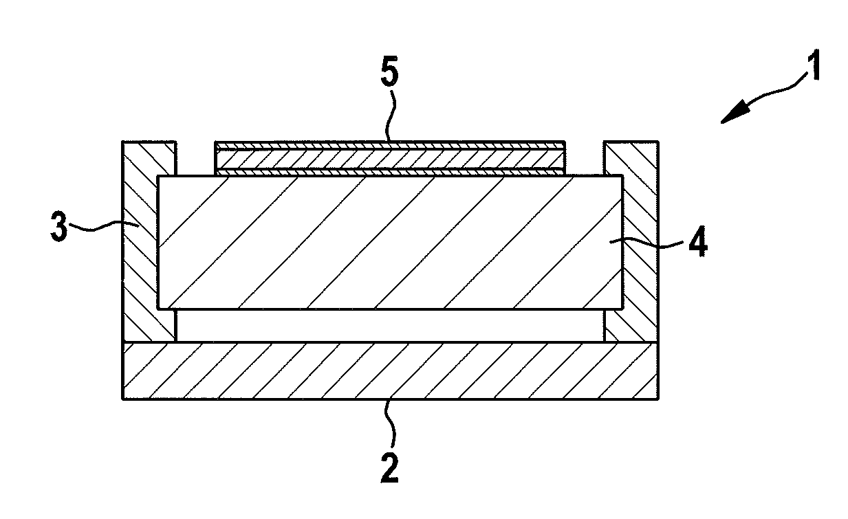
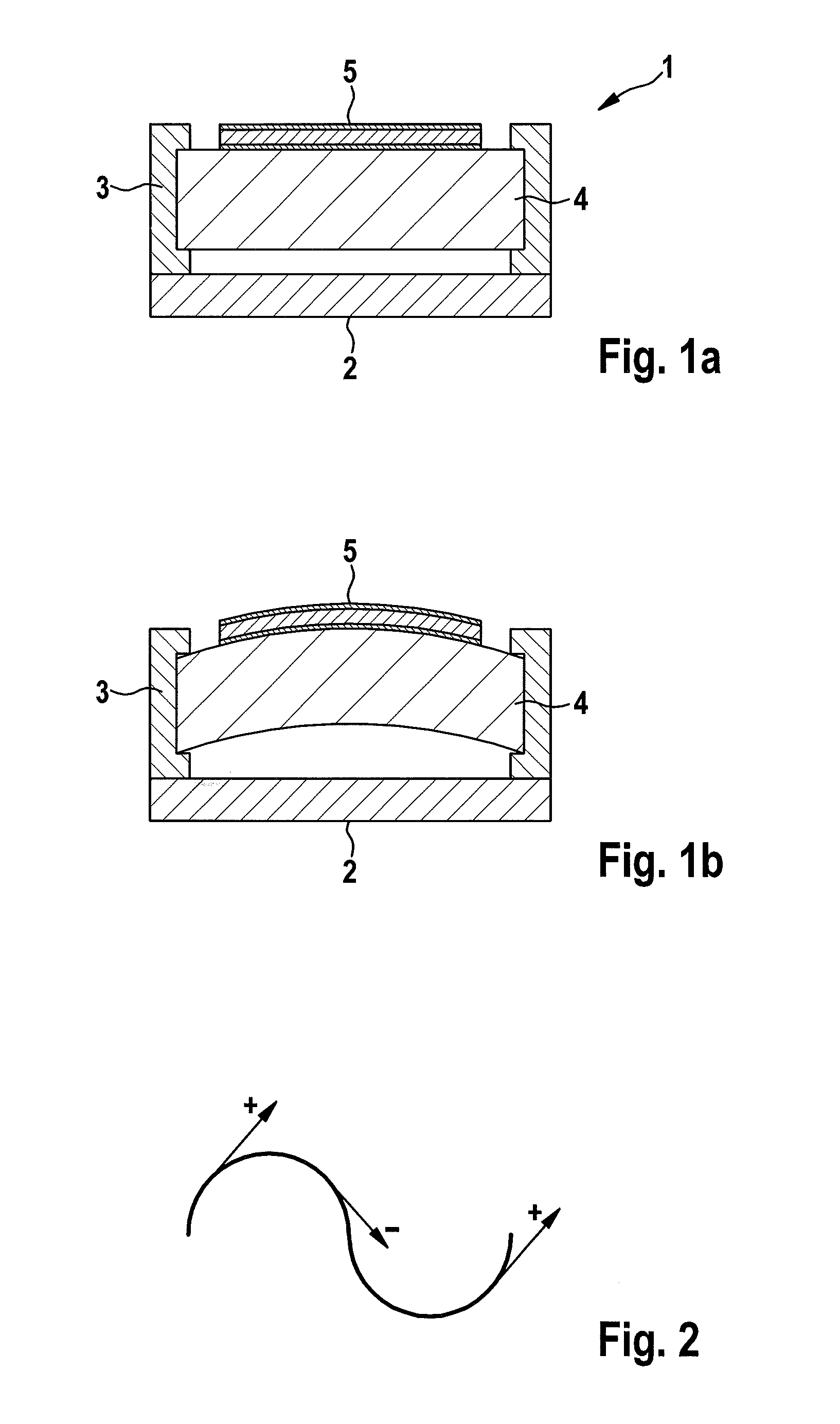
[0039]FIG. 1a shows the schematic cross section of a conventional sound transducer design 1 including a component surface 2 on the rear side of the transducer, two frames or mountings 3 on the two sides of the sound transducer foil composite including a carrier layer 4 and, situated thereabove, a composite 5 made up of a piezoelectric layer and two electrode layers. The surface of the sound transducer foil is not structured, and the foil is clamped straight between the mountings 3. This results in a constant surface slope of the sound transducer foil.

[0040]FIG. 1b shows the schematic cross section of a conventional sound transducer design including a sound transducer foil composite made up of a carrier layer 4 and, situated thereabove, a piezoelectric layer and two electrode layers 5. The surface of the sound transducer foil is not structured. The composite is clamped between mountings 3 in a curved manner. This results (from left to right) first in a positive slope of the sound tra...


PUM


Abstract

An electroactive sound transducer foil includes a composite foil made up of at least one carrier foil, at least one first and one second electrode, and at least one piezoelectric layer including an electroactive polymer, the surface of the sound transducer foil including a structuring having different slopes, and the slope of the sound transducer foil surface changing the sign at least twice.

Description

FIELD OF THE INVENTION[0001]The present invention relates to an electroactive sound transducer foil including a composite foil made up of at least one carrier foil, at least one first and one second electrode, and at least one piezoelectric layer including an electroactive polymer, the surface of the sound transducer foil including a structuring having different slopes and the slope of the sound transducer foil surface changing the sign at least twice.BACKGROUND INFORMATION[0002]Established electrodynamic sound transducer concepts usually use diaphragms which are centrally connected to an electromagnetic voice coil and are caused to vibrate either by Lorentz forces induced by current flow or by air movements. Depending on the operating mode, either an electric current is converted into mechanical movement or a diaphragm movement is converted into an electric current. With these design forms, for example, moving coil loudspeakers or microphones are obtainable, which today are charact...

Claims


Application Information

Patent Timeline
IPC IPC(8): H04R17/00
CPCH04R17/00
Inventor GERLACH, ANDRE
Owner ROBERT BOSCH GMBH
Why Eureka
Try Eureka