
Mechanical system that fluidizes, mixes, coats, dries, combines, chemically reacts, and segregates materials

a mechanical system and fluidizer technology, applied in the direction of mixing, vibration, transportation and packaging, etc., can solve the problems of insufficient uniform motion of fluidizers and tumblers, and insufficient mixing of materials. to achieve the effect of facilitating bulk mixing

Active Publication Date: 2015-05-28
RESODYN CORP
View PDF6 Cites 24 Cited by
  • Summary
  • Abstract
  • Description
  • Claims
  • Application Information

AI Technical Summary

Benefits of technology

The patent describes a system for mixing materials using vibratory mixing technology. The system includes an acoustic means for generating a fluidized bed in a mixing vessel, which can mix materials without the use of mixing blades or impellers. The system can induce both micro-mixing and bulk mixing of the materials, and can be controlled to achieve desired outcomes for various applications. The system can also include a sprayer for introducing materials into the mixing vessel, a vacuum line for creating pressure in the mixing vessel, and a pressure relief valve to control pressure levels. The system can also include a cooling jacket for cooling the mixing vessel and a heating jacket for heating it. The patent also describes a near infrared (NIR) sensor to detect mixedness of the materials in the mixing vessel.

Problems solved by technology

Current methods and systems for spray coating applications do not produce uniformly mixed, coated or combined materials.
These methods have particular difficulty when trying to coat smaller particles uniformly.
Many fluidizers and tumblers do not adequately create a uniform motion to coat the materials evenly.
Similarly, current methods for combining materials using chemical reactions are costly and time consuming.
Under traditional methods, excess reaction gas can be wasted because the reaction gas is used for both fluidization as well as reaction.
The other materials added with conventional fluidizers would potentially add contaminants, as well as waste materials that would have normally been reacted.

Method used


Image

  • Mechanical system that fluidizes, mixes, coats, dries, combines, chemically reacts, and segregates materials
  • Mechanical system that fluidizes, mixes, coats, dries, combines, chemically reacts, and segregates materials
  • Mechanical system that fluidizes, mixes, coats, dries, combines, chemically reacts, and segregates materials

Examples


Embodiment Construction

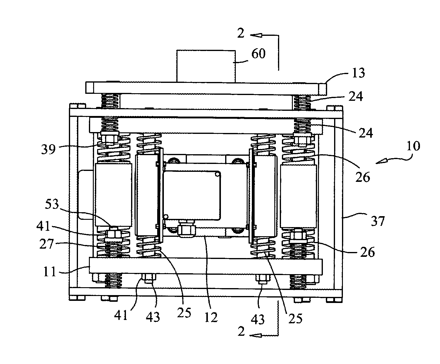
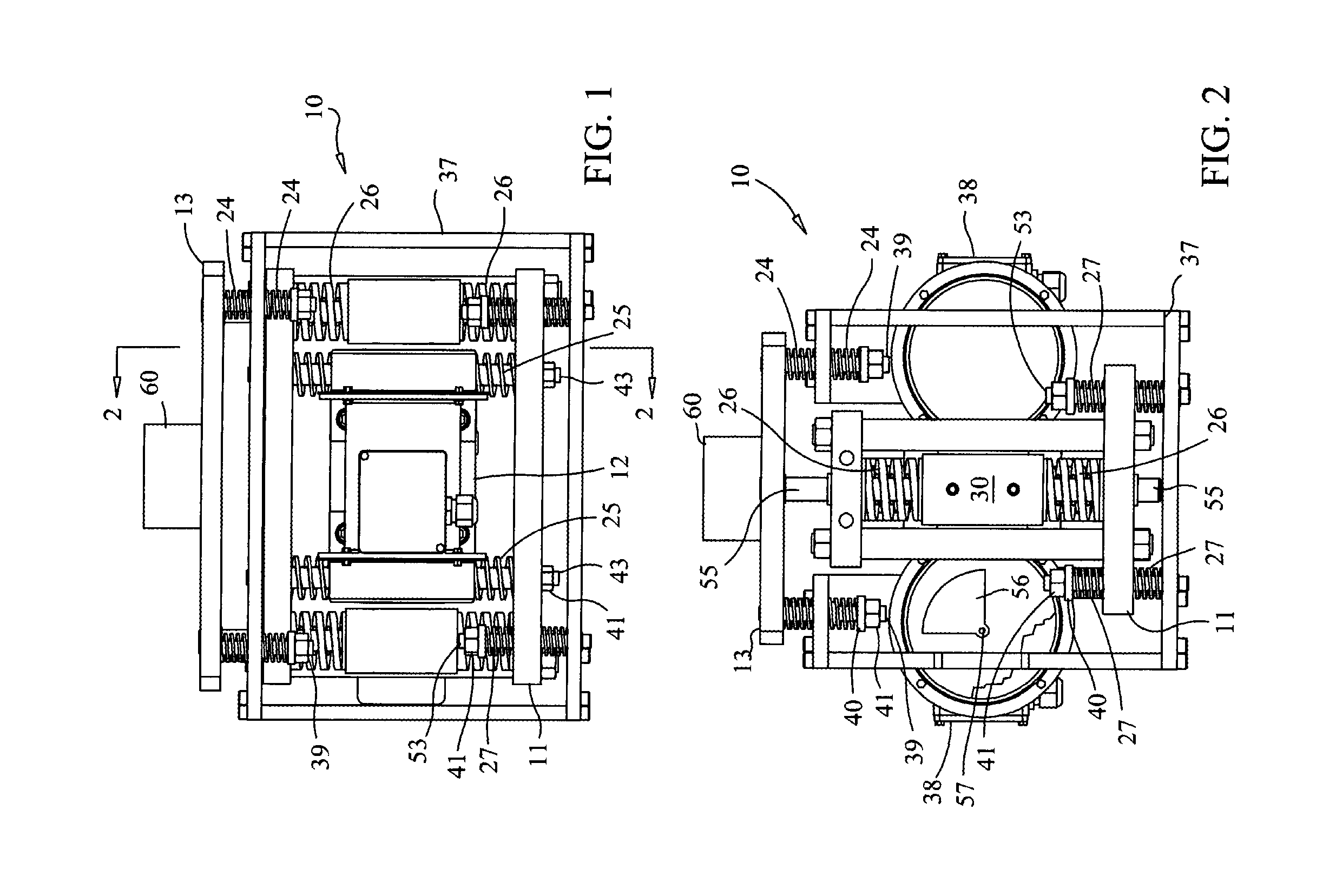
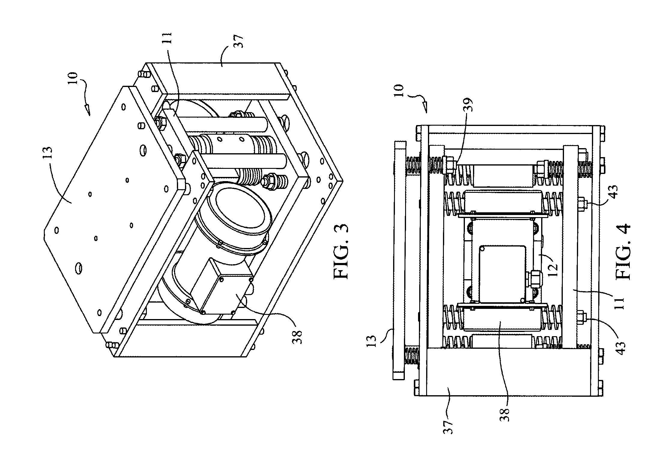
[0042]FIGS. 1-4, show various views of examples of flat plate resonant mixer 10. The resonant mixer 10 includes three independent movable masses (intermediate mass 11, oscillator mass 12 and payload 13) and four distinct spring beds or spring systems (payload mass to ground springs 24, oscillator to intermediate mass springs 25, intermediate mass to payload springs 26 and intermediate mass to ground springs 27) that are housed in a rigid structure 7. The oscillator mass 12 is situated between the other two masses. The intermediate mass 11 is situated below the oscillator mass 12. The payload 13 is situated above the oscillator mass 12. In some implementations, all of the masses are constructed of steel or some comparable alloy.

[0043]The oscillator mass 12 is rigidly connected to two oscillator drives 38 (e.g., two direct current (DC) servo motors) and is movably connected to the intermediate mass 11 by the oscillator to intermediate mass alignment struts 43, the oscillator to interm...


PUM


Abstract

The present application is directed towards systems for adding components to materials being fluidized in a vibratory mixer by use of atomizers or sprayers. A mechanical system can fluidizes, mix, coat, dry, combine, or segregate materials. The system may comprise a vibratory mixer, mixing vessel containing a first material and a sprayer to introduce a second material. The vibratory mixer may generate a fluidized bed of a first material and the sprayer, coupled to the mixing vessel, may introduce a second material onto the fluidized bed to mix the materials in a uniform and even fashion.

Description

RELATED APPLICATIONS[0001]The patent application claims priority to U.S. Patent Application No. 61 / 689,256, filed on May 31, 2012, entitled “Mechanical System That Fluidizes, Mixes, Coats, Dries, Combines, Chemically Reacts, or Segregates Materials.” The disclosure of the prior applications is considered part of and is incorporated by reference in this patent application.FIELD[0002]The present application is in the technical field of coating, drying, and mixing particles.BACKGROUND[0003]Current methods and systems for spray coating applications do not produce uniformly mixed, coated or combined materials. These methods have particular difficulty when trying to coat smaller particles uniformly. Many fluidizers and tumblers do not adequately create a uniform motion to coat the materials evenly. Similarly, current methods for combining materials using chemical reactions are costly and time consuming. Under traditional methods, excess reaction gas can be wasted because the reaction gas ...

Claims


Application Information

Patent Timeline
Patent Type & Authority Applications(United States)
IPC IPC(8): B01F11/00B01F15/06B01F15/00B01F13/00B01F15/02
CPCB01F11/0025B01F13/0059B01F15/0254B01F2015/061B01F15/06B01F15/00175B01F15/00207B01F15/00357B01J2/006B01J2/04B01J2/18B01F31/60B01F31/25B01F31/24B01F33/30B01F35/90B01F35/213B01F35/2115B01F35/2213B01F35/7179B01F31/265B01F2035/98
Inventor LUCON, PETER A.FARRAR, LAWRENCE C.
Owner RESODYN CORP
Learn More