Method for shaping a film of a material that has low resistance to traction, and mirror comprising such a film

a technology of traction resistance and film, which is applied in the direction of solar energy, glass reforming apparatus, solar-ray concentration, etc., can solve the problems of forming the mirror, the glass sheet that it comprises as reflector elements, and the method is therefore energy-intensiv

Inactive Publication Date: 2015-05-21
HELIOCLIM
View PDF2 Cites 2 Cited by
  • Summary
  • Abstract
  • Description
  • Claims
  • Application Information

AI Technical Summary

Benefits of technology

[0056]Thanks to these provisions, the method for shaping a glass sheet that is the subject of the present inventi

Problems solved by technology

Shaping the mirror and, where applicable, the glass sheet that it comprises as reflector element, is a problem.
However, during the step 120, the temperature of the mirrors is raised to the deformation temperature of the glass, i.e. close to 600° C. This method is therefore energy-intensive.
In addition, the mirrors intended to collect the solar energy being generally large, it therefore appears that the method can require large-size furnaces in line with the size of the mirror.
When such glass needs to be hardened by tempering, because of the sizes of the glass sheets, for example cylindrical parabolic in shape, these tempering operations appear difficult to implement without the risk of breaking a large number of glass sheets thus curved according to the method.
This hot shaping must be carried out before the reflective coating is applied since the latter usually does not support the deformation temperatures of the glass.
In addition, this step of applying the reflective coating must be performed on a non-flat shape, which requires special tools and generates significant costs.
These reflectors are therefore very heavy, which makes them unsuitable for installations off

Method used


Image

  • Method for shaping a film of a material that has low resistance to traction, and mirror comprising such a film
  • Method for shaping a film of a material that has low resistance to traction, and mirror comprising such a film
  • Method for shaping a film of a material that has low resistance to traction, and mirror comprising such a film

Examples


Embodiment Construction

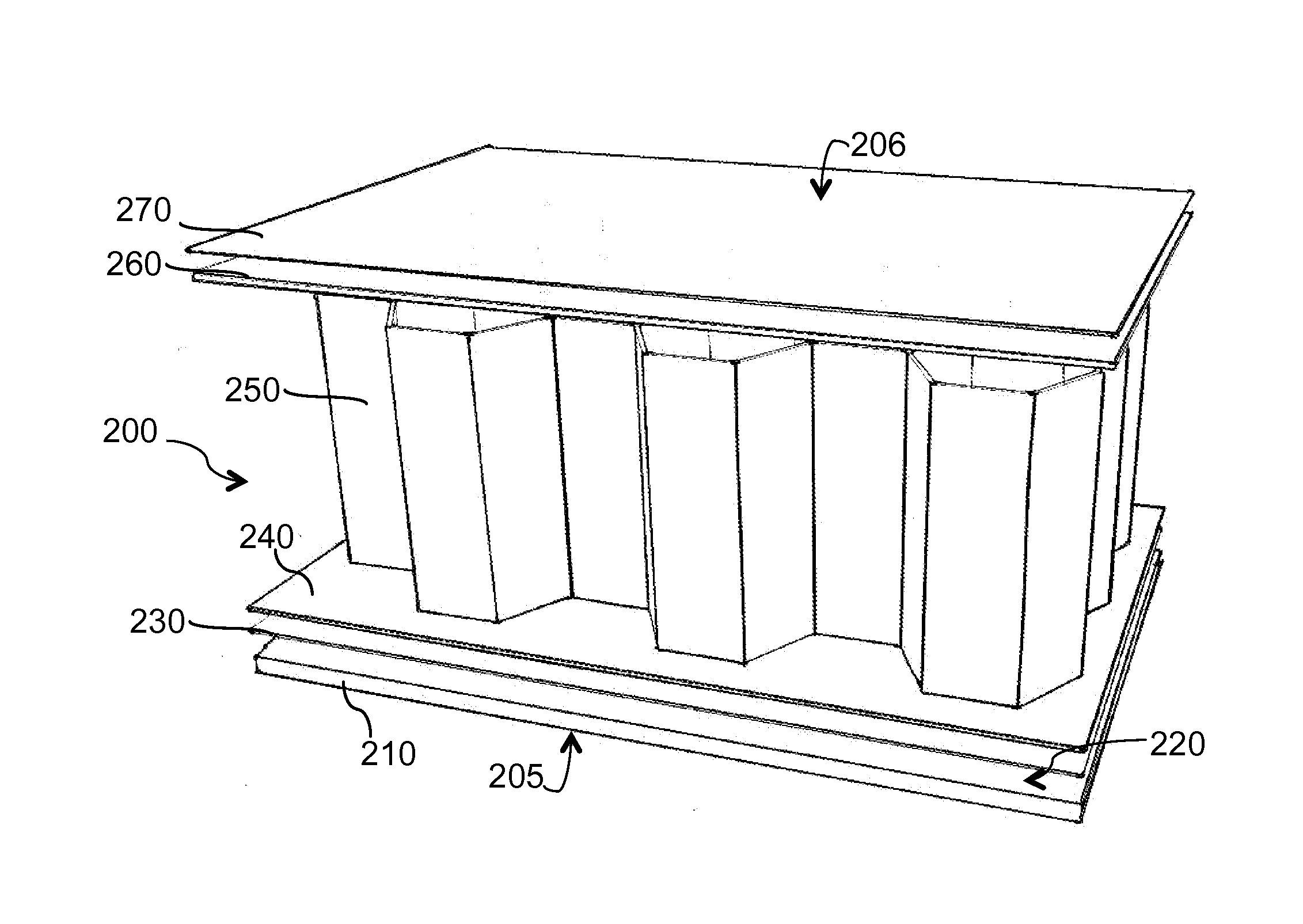
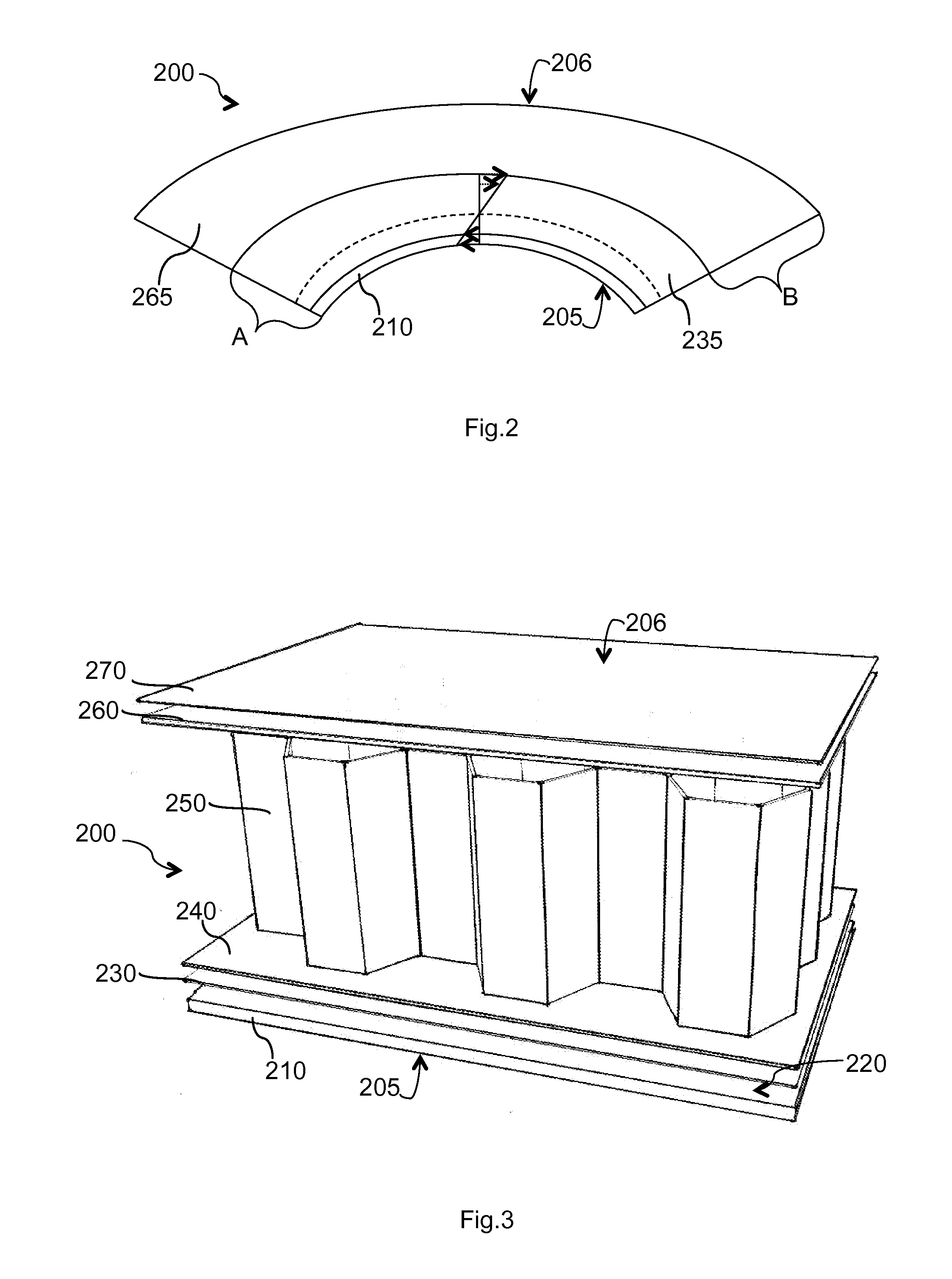
[0080]It is noted that in FIG. 2 and FIG. 3 the various components of the mirror are not shown to scale. In fact, a curvature of FIG. 2 is exaggerated in order to highlight physical phenomena and the thicknesses of the various layers are not to scale. In addition, only a small portion of the mirror of FIG. 3 is shown in order to facilitate understanding.

[0081]Thus, in FIG. 2, one can see a mirror 200 that is the subject of the invention comprising an assembly of materials in successive layers from a front surface 205 of the mirror towards a rear surface 206 of the mirror. Complex A consists of: a glass sheet, possibly coated by a reflective coating and a layer of a first material. Element B is an element allowing A to be stabilized in the required shape.

[0082]Reflective element A itself comprises a reflective glass sheet 210, on a rear surface of which a front layer of a structural material 235 is fixed.

[0083]The reflective characteristic of element A comes from properties of the gl...


PUM

PropertyMeasurementUnit
Fractionaaaaaaaaaa
Thicknessaaaaaaaaaa
Pressureaaaaaaaaaa

Abstract

A method for shaping a glass sheet having a thickness Ev by applying and adhering a layer of a first material that can be subjected to traction onto a first surface of the glass sheet. The layer has a thickness E1. Either the neutral fiber of the complex moves across into the layer of the first material, the glass being then completely under compression; or the neutral fiber moves towards the first material but remains in the glass sheet, the surface of the glass being then subjected to a level of traction lower than the failure value. The complex comprising the glass sheet coated with the first layer of material is deformed, such that it is close to the final shape and the glass is mainly under compression. A stabilizing element B is applied and adhered or attached onto the complex A and of dimensionally stabilizing the final shape.

Description

FIELD OF THE INVENTION[0001]The present invention relates to a method for shaping a sheet of material that has low resistance to traction, for example glass, and a mirror comprising such a sheet.[0002]The invention also relates to a mirror for concentrating solar energy, in particular for inclusion in a device for transforming solar energy into electrical or thermal energy, in particular by reflecting, concentrating or focusing the solar energy by means of a mirror, comprising a sheet shaped by the method, towards a collector of heat or electrical energy.[0003]In the case of thermal use, the method described in the present invention allows a device to be realized, said device allowing a heat-transfer fluid (water, water with additive, oil or other) to be heated for various applications, for example to supply an air-conditioning device, to produce heat for industry, agri-food or other direct or indirect use of the heat thus produced.TECHNOLOGICAL BACKGROUND[0004]Several ways of colle...

Claims


Application Information

Patent Timeline
IPC IPC(8): F24J2/10G02B19/00B32B37/14B32B38/00C03B23/03H01L31/054F24S23/70
CPCF24J2/1057C03B23/0305H01L31/0547G02B19/0042B32B38/0012G02B19/0019G02B19/0023B32B37/14B32B17/067B32B38/1866B32B2305/024B32B2315/08C03C17/3663C03C17/38C03C23/007F24S23/82G02B5/10Y02E10/40Y02E10/52Y10T156/1044Y10T156/1048
Inventor GODILLOT, YANNICKNGHIEM, MARIEPES, MICHAELDANIEL, CHARLESVITUPIER, YANN
Owner HELIOCLIM
Why Eureka
Try Eureka