
Variable geometry lift fan mechanism

a technology of lift fan and variable geometry, which is applied in the direction of machines/engines, vertical landing/take-off aircraft, transportation and packaging, etc., can solve the problems of reducing the performance of aircraft, reducing the aerodynamic drag of fans of more than two blades, and reducing the frontal area of the lift fan and the drag produced by the lift fan. , to achieve the effect of reducing the overall width of the aircraft, reducing the frontal area of the lift fan and reducing

Active Publication Date: 2015-05-14
WISK AERO LLC
View PDF7 Cites 10 Cited by
  • Summary
  • Abstract
  • Description
  • Claims
  • Application Information

AI Technical Summary

Benefits of technology

The patent describes a lift fan of a powered-lift aircraft that can change from a deployed configuration to a collapsed configuration and back again. The collapsed configuration reduces the frontal area and drag of the lift fan, making it easier to transport and store the aircraft. The technical effect is improved efficiency and versatility in the design of the lift fan for powered-lift aircraft.

Problems solved by technology

When the fan blades are stationary, these types of fans produce large amounts of aerodynamic drag due to flow separation and large frontal area from the blades.
This reduces the performance of the aircraft.
While a two-bladed fan can be stopped with the blades aligned in the flow direction, this is not possible with fans of more than two blades.

Method used


Image

  • Variable geometry lift fan mechanism
  • Variable geometry lift fan mechanism
  • Variable geometry lift fan mechanism

Examples


Embodiment Construction

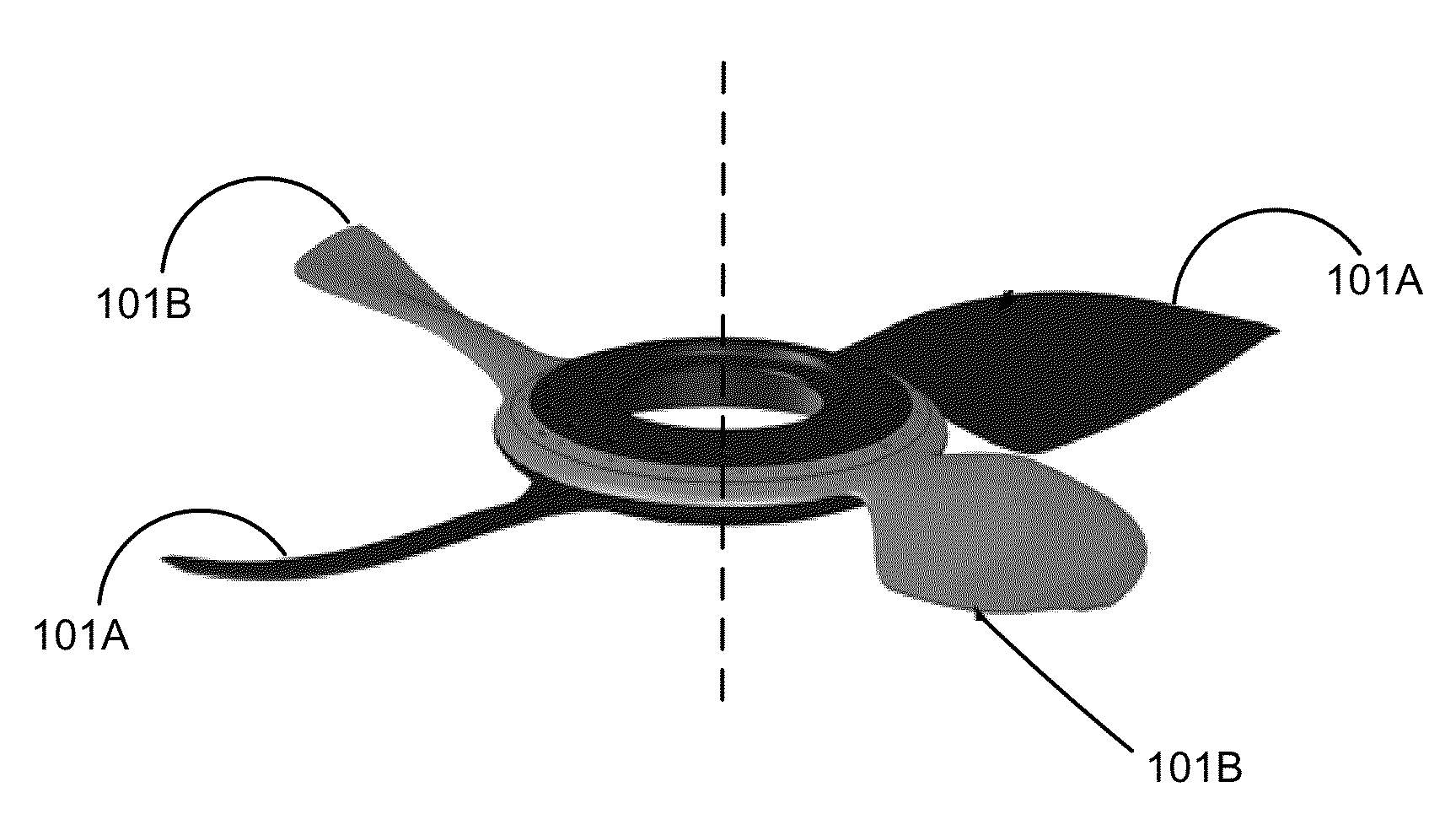
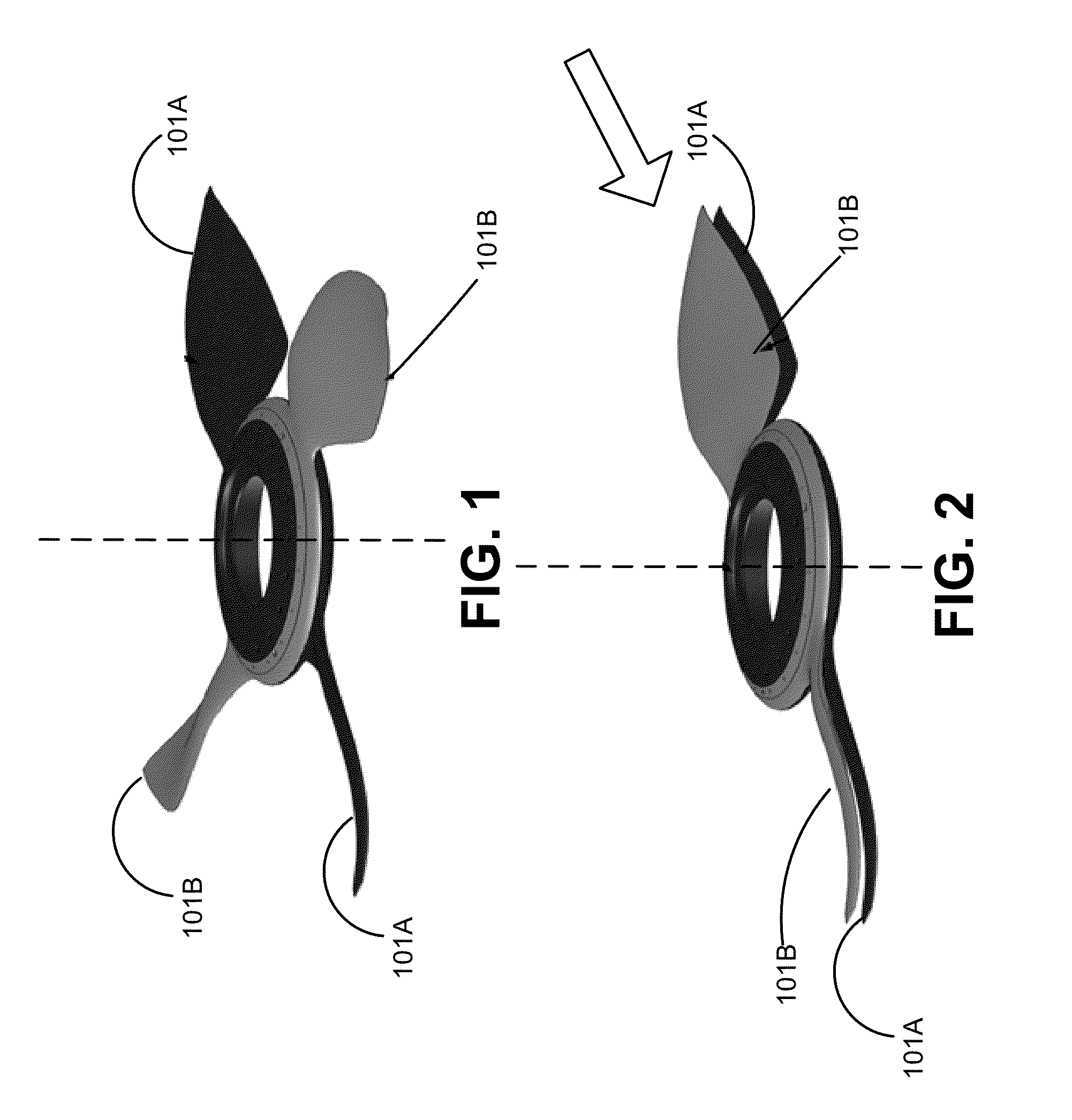
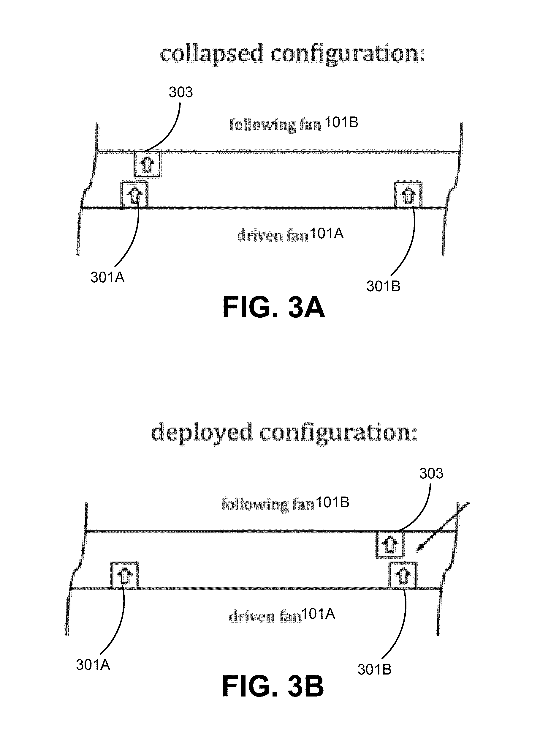
[0018]FIG. 1 illustrates a lift fan of a powered-lift aircraft according to one embodiment. In the illustrated embodiment, the lift fan comprises a stack of two or more sets of one or two fan blades, where the total number of blades is equal to the number needed in a baseline fixed-blade fan. Particularly, FIG. 1 illustrates a stack of two two-blade sets, for a total of four fan blades. The configuration shown in FIG. 1 is referred to as the deployed configuration. In one embodiment, when the lift fan is producing thrust, the blades sets are rotated to their optimal thrust producing orientation as shown in FIG. 1. In FIG. 1, blade set 101A represents a driven set of blades that is attached to a drive source such as an electric motor and blade set 101B represents one or more additional following set of blades that are coupled to the driven blade set by a mechanism allowing motion about the axis of rotation. The following set of blade sets may include one additional set of blades or t...


PUM


Abstract

A vertical takeoff and landing aircraft includes rotors that provide vertical and horizontal thrust. During forward motion, the vertical lift system is inactive. A lift fan mechanism positions the fan blades of the aircraft in a collapsed configuration when the vertical lift system is inactive and positions the fan blades of the aircraft in a deployed configuration when the vertical lift system is active.

Description

CROSS-REFERENCE TO RELATED APPLICATIONS[0001]This application claims priority to U.S. Provisional Patent Application No. 61 / 693,172 filed on Aug. 24, 2012, which is incorporated by reference in its entirety.BACKGROUNDField[0002]Described embodiments relate to a variable geometry lift fan mechanism for a powered-lift aircraft.[0003]Aircraft may use fixed wings, such as in a conventional airplane, rotary wings, such as in a helicopter, or a combination of fixed wings and rotary wings. Powered-lift aircraft, which derive lift in some flight regimes from rotary wings and in others from fixed wings, are desirable because they are able to perform very short or vertical takeoffs and landings. A powered-lift aircraft may have rotary wings, or rotors, that provide both vertical and horizontal thrust. Other types of powered-lift aircraft have one or more rotors (lift fans) for vertical thrust, and one or more rotors (propellers) for horizontal thrust. In some powered-lift aircraft the lift fa...

Claims


Application Information

Patent Timeline
Patent Type & Authority Applications(United States)
IPC IPC(8): F04D19/02
CPCF04D19/02B64C11/00B64C11/16B64C11/28B64C27/20B64C11/48B64C27/022B64C27/50
Inventor LONG, GEOFFREY A.LYASOFF, RODIN
Owner WISK AERO LLC
Learn More