Vehicle engine control system

a technology of vehicle engine and control system, which is applied in the direction of electric control, charge feed system, fuel injection apparatus, etc., can solve the problem of difficulty for the microprocessor to correct the threshold value of comparison determination, and achieve the effect of reducing the speed of control load and raising the control accuracy of fuel injection

Inactive Publication Date: 2015-05-14
MITSUBISHI ELECTRIC CORP
View PDF12 Cites 7 Cited by
  • Summary
  • Abstract
  • Description
  • Claims
  • Application Information

AI Technical Summary

Benefits of technology

[0018]The first objective of the present invention is to provide a vehicle engine control system in which for the purpose of controlling the excitation current of the electromagnetic coil for fuel injection, there is provided an auxiliary control circuit unit that collaborates with a microprocessor, thereby reducing rapid control load on the microprocessor, and in which the microprocessor can readily adjust the control characteristics of the excitation current so that the control accuracy in fuel injection can be raised.
[0019]The second objective of the present invention is to provide a vehicle engine control system in which the state of controlling the excitation current is constantly monitored so that for a disturbance including the fluctuation of the electromagnetic coil due to a temperature change therein, the control accuracy in fuel injection can be maintained without increasing the rapid control load on the microprocessor.
[0034]Accordingly, by use of a setting value register, the microprocessor can readily adjust setting data that serves as a control constant; the auxiliary control circuit unit performs logic control in which the opening / closing of a plurality of power supply control opening / closing devices is controlled in synchronization with the engine rotation, and stores monitoring information related to the generation state of a rapid excitation current; the microprocessor performs calculation control based on the monitoring storage information provided from the auxiliary control circuit unit and can perform correction control so as to obtain a desired fuel injection amount. Therefore, there is demonstrated an effect that the rapid control load on the microprocessor is reduced and hence the accuracy of fuel injection control can be raised.

Problems solved by technology

In this case, the comparison determination threshold value to be inputted to the comparison circuit is generated based on an analogue reference voltage; therefore, it is difficult for the microprocessor to correct the comparison determination threshold value.

Method used


Image

  • Vehicle engine control system
  • Vehicle engine control system
  • Vehicle engine control system

Examples


embodiment 1

(1) Detailed Description of Configuration

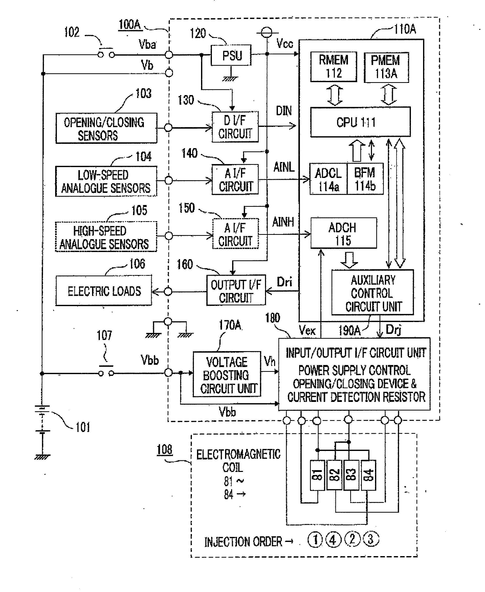
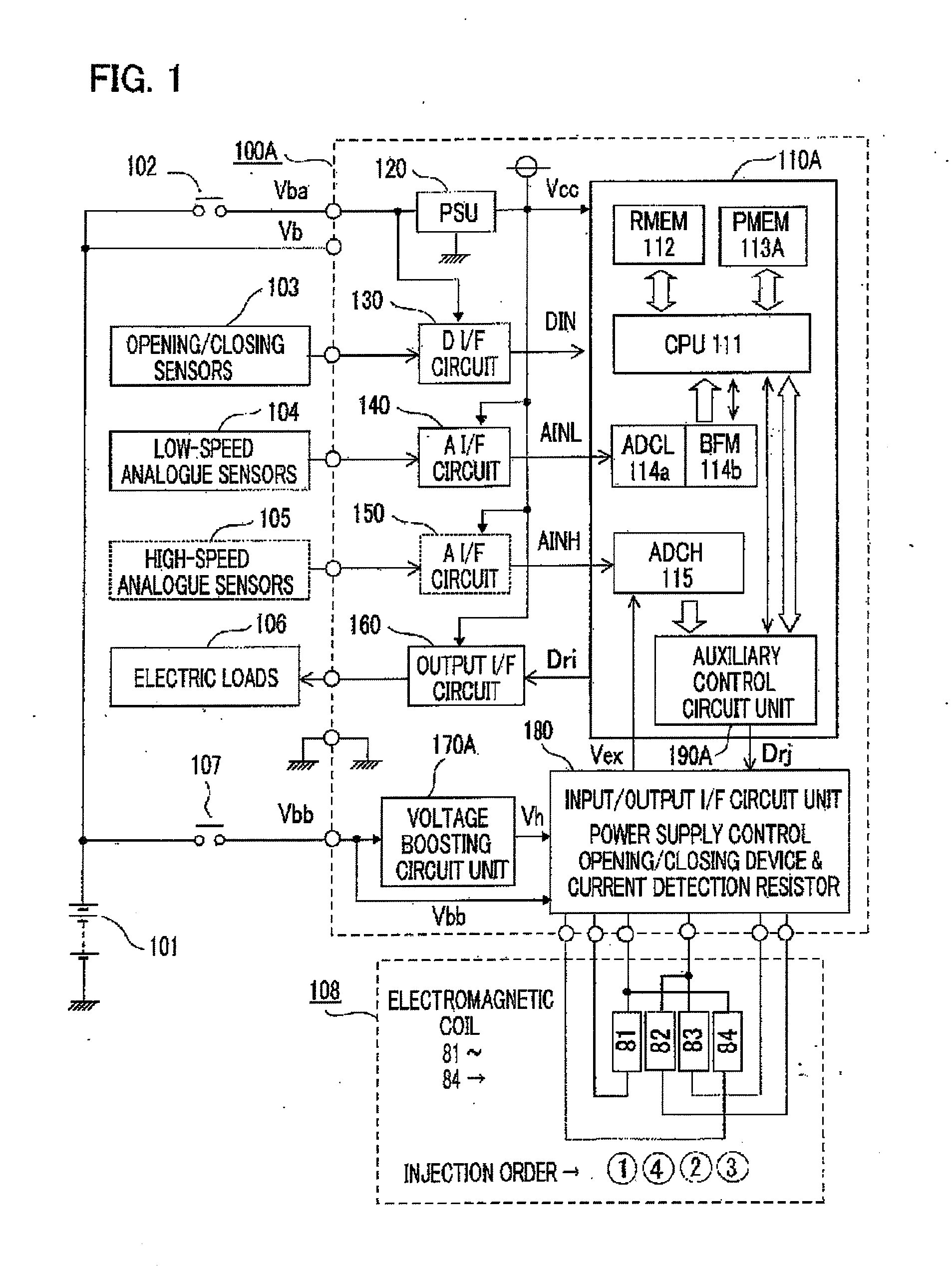
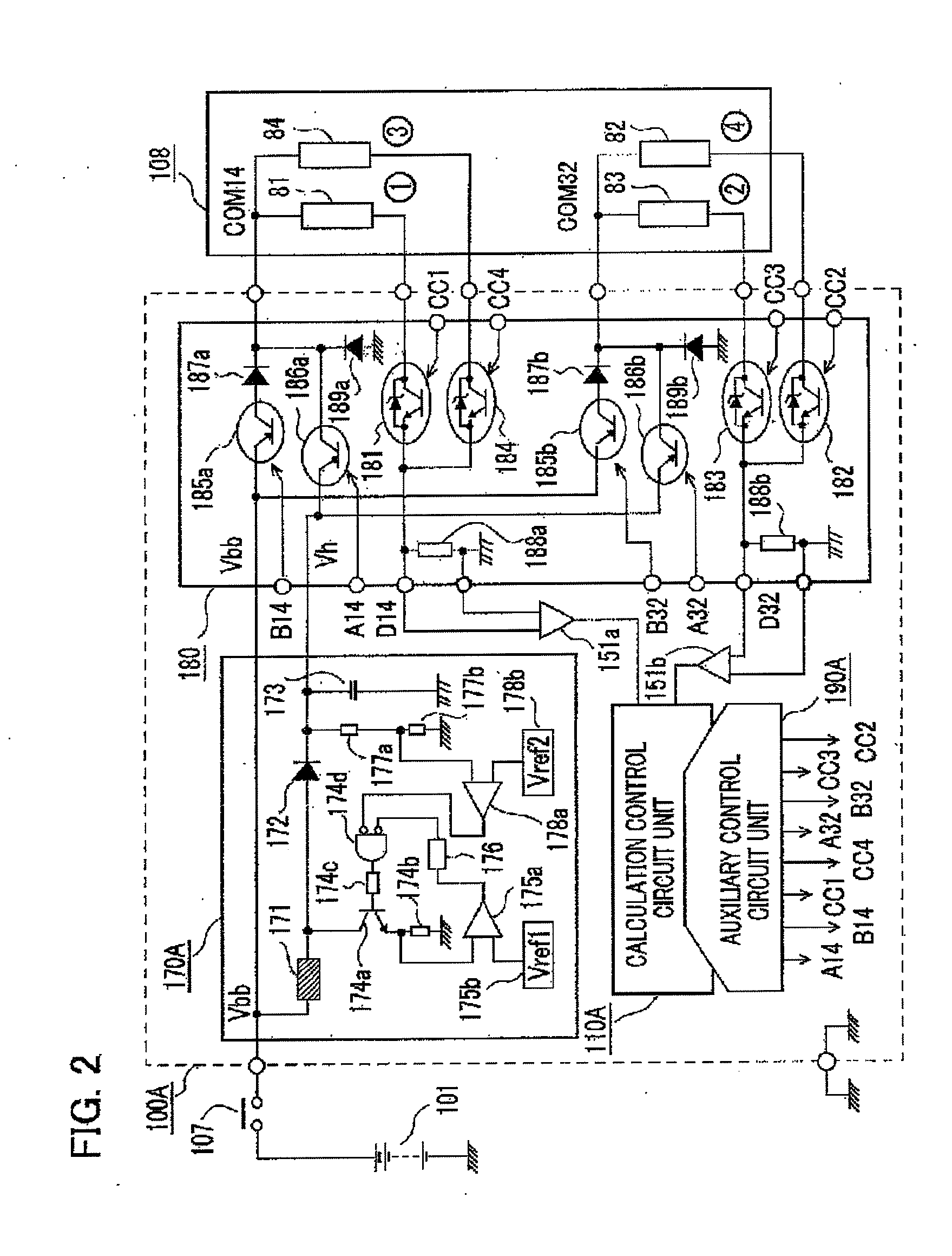
[0047]Hereinafter, there will be explained a vehicle engine control system according to Embodiment 1 of the present invention. FIG. 1 is a block diagram illustrating the overall configuration of a vehicle engine control system according to Embodiment 1 of the present invention. In FIG. 1, a vehicle engine control system 100A is configured mainly with a calculation control circuit unit 110A configured as a one-chip or two-chip integrated circuit device, an input / output interface circuit unit 180 for after-mentioned electromagnetic coils 81 through 84 provided on respective fuel-injection electromagnetic valves, and a voltage boosting circuit unit 170A that functions as a high-voltage power source for rapidly exciting the electromagnetic coils 81 through 84.

[0048]At first, a vehicle battery 101 connected with the outside of the vehicle engine control system 100A directly supplies a battery voltage Vb to the vehicle engine control system 100A an...

embodiment 2

(1) Detailed Description of Configuration

[0126]Next, there will be explained a vehicle engine control system according to Embodiment 2 of the present invention. FIG. 6 is a block diagram illustrating the overall configuration of a vehicle engine control system according to Embodiment 2 of the present invention. Hereinafter, the difference between a vehicle engine control system according to Embodiment 2 and the vehicle engine control system according to Embodiment 1, illustrated in FIG. 1, will mainly be explained.

[0127]The main differences between a vehicle engine control system 100B according to Embodiment 2 and the vehicle engine control system 100A according to Embodiment 1 are that in the vehicle engine control system 100B, a microprocessor sets in a variable manner the boosted high voltage Vh generated by a voltage boosting circuit unit 170B and hence a third correction control unit 938 is utilized instead of the second correction control unit 528 and that in the vehicle engin...


PUM


Abstract

A calculation control circuit unit 110A is provided with a microprocessor 111, an auxiliary control circuit unit 190A, and a high-speed A / D converter 115 to which the detection signals of excitation currents for electromagnetic coils 81 through 84 are inputted; based on an valve-opening command signal generated by the microprocessor 111 and excitation-current setting information, the auxiliary control circuit unit 190A opening / closing-controls power supply control opening / closing devices by use of a numeral value comparator and a dedicated circuit unit, and monitors and stores at least one of the peak value of a rapid excitation current and a peak current reaching time; the microprocessor 111 performs correction control with reference to the monitoring storage data, and implements fuel injection control while reducing a rapid control load on the microprocessor 111.

Description

CROSS-REFERENCE TO RELATED APPLICATION[0001]This application is a divisional of U.S. application Ser. No. 13 / 766,013 filed Feb. 13, 2013, which is the disclosure of which is incorporated herein by reference in its entirety.BACKGROUND OF THE INVENTION[0002]1. Field of the Invention[0003]The present invention relates to a microprocessor-incorporated vehicle engine control system in which, in order to rapidly drive the fuel-injection electromagnetic valve of an internal combustion engine, a boosted high voltage is instantaneously supplied from a vehicle battery to the electromagnetic coil for driving the electromagnet valve and valve-opening holding control is performed by means of the voltage of the vehicle battery; in particular, the present invention relates to a vehicle engine control system in which while the high-speed control load on the microprocessor is reduced, the control accuracy in fuel injection is raised.[0004]2. Description of the Related Art[0005]It is widely put into ...

Claims


Application Information

Patent Timeline
Patent Type & Authority Applications(United States)
IPC IPC(8): F02D41/20F02M51/06F02D41/30
CPCF02D41/20F02D2041/202F02M51/06F02D41/30F02D2041/2003F02D2041/2027F02D2041/2055F02D41/28
Inventor NISHIDA, MITSUNORINISHIZAWA, OSAMU
Owner MITSUBISHI ELECTRIC CORP
Why Eureka
Try Eureka